
R: 9509 final
University of Surrey

R: 9509 final | University of Surrey |
November 1995
Lloyd WOOD
L.Wood@surrey.ac.uk
http://www.ee.surrey.ac.uk/Personal/L.Wood/
MSc in Satellite Communication Engineering, 1994-95
University of Surrey
Supervisors:
| Professor Barry EVANS | Professor Gérard MARAL |
| B.Evans@ee.surrey.ac.uk | Maral@tlse.enst.fr |
| http://www.ee.surrey.ac.uk/showstaff?B.Evans | |
|
Centre for Satellite Engineering Research University of Surrey Guildford GU2 5XH England, UK |
TELECOM Paris site de Toulouse BP 4004 31028 Toulouse Cedex FRANCE |
| http://www.ee.surrey.ac.uk/CSER/ | http://www.enst.fr/depts/tsa/ |
This report copyright (C) Lloyd Wood 1995-1998
This document also available in Adobe Acrobat portable document format (pdf) from:
http://www.ee.surrey.ac.uk/Personal/L.Wood/publications/
Please be aware that superscript and subscript tags are used
Ecole Nationale Supérieure des Télécommunications (ENST)
- site de Toulouse
Enseignment Supérieur de France Télécom
Non-geostationary-orbit satellite constellation networks have been proposed as a means of providing high-quality, low-delay communications to handheld portable devices, usually in remote areas with no ground communications infrastructure, anywhere in the world. Iridium, originally proposed by Motorola, and Teledesic, originally proposed by the Calling Corporation, are two planned satellite constellations that are also self-contained networks.
The networking requirement for intersatellite links means that the type of constellation of most interest to us has circular orbits, to allow fixed pointing of intra-plane links to satellites fore and aft at different phases in the same orbital plane. Circular orbits also avoid the zooming effect of the satellite footprint, simplifying aspects of ground coverage.
Ideally, these circular orbits are high-inclination and near-polar, so that minimal control of pointing of antennae is required to maintain the inter-plane links and minimal Doppler shift is experienced. Orbits of the same inclination do not suffer from differential precession. Near-polar orbits allow global or near-global coverage.
Performance should be examined by both analysis and simulation. An analytical model, drawing on established networking theory, should be produced and verified with the use of simulation tools, such as Matlab or Opnet. Beginning with a homogeneous model, the simulations should aim to become as realistic as possible, and should consider factors such as propagation delay, population density and distribution of calls with distance and with time. The performance of protocol standards likely to be implemented in such a network, such as ATM and B-ISDN, should be considered and included in the simulations.
A short report was submitted to the University of Surrey at the end of August, 1995 for assessment and award of the MSc. This report is submitted at the end of the placement, in October 1995, and covers all research undertaken during the placement.
A review of graph theory and analysis has shown that the class of network constellation of interest takes the topological form of a ring with two half-twists mapping onto a sphere which is the Earth. This shape is imposed by the physical constraints of orbital mechanics.
This shape requirement conflicts with the previously-taken approach of starting with the homogeneous model, which assumes a seamless network that each node sees in the same way.
The concepts of single and double network coverage are introduced. A homogeneous model must be seamless, and so has double network coverage, as a torus is folded onto a sphere due to the limitations of orbital mechanics. The ring shape has single network coverage, and is therefore seamed thanks to orbit limitations, so the homogeneous model is not applicable to it.
It has been found necessary to describe and model the seamed network directly. A minimum-path fewest-hops-necessary approach to routing through the network has been considered, and Matlab programs describing and comparing network shapes in terms of the number of minimum paths per node, for four and eight links per node, have been written.
These programs are capable of being built on to make a complete routing model of the ring network, circumventing the problematic homogeneous approach.
Rather than work from the satellite-networking theory laid out in these papers and use it to build realistic simulations, it has been found necessary to work from first principles, together with known computer networking theory, to attempt to establish a sound analytical model.
This has required a much more extensive literature survey than originally expected, reaching the area of bi-directional Manhattan networks, a type of computer network directly relevant to the double-network-coverage case. This survey led the author into unexpected and unfamiliar areas of graph theory and computer networking, and has considerably delayed the creation of useful simulations.
Some basic analysis has been possible, but this analysis is only suited to the homogeneous (seamless or infinite network) approach, and not to the finite, seamed, case of interest.
Figure 3.1: Links from a node
Figure 3.2: Single orbital plane
Figure 3.3: Repeating-pattern mesh networks
Figure 3.4: Network topology of Iridium
Figure 3.5: How each Teledesic node sees its immediate neighbours
Figure 3.6: Pascal's triangle for minimum paths
Figure 3.7: Mapping Pascal's triangle around the source node
Figure 3.8: Shearing the Pascal's grid
Figure 3.9: Determining network diameter
Figure 3.9a: Fourway and eightway connectivity
Figure 3.9b: Threeway connectivity
Figure 3.9c: Sixway connectivity
Figure 4.1:  k and
k and  k+
shown graphically
Figure 5.1: Minimum paths through a node as the multiples of two grids
Figure 5.2: Minimum paths through multiple fixed points
Figure 5.3: Maximal cut across a grid
Figure 5.4: Counting minimum paths and traffic through a node by rotational symmetry
Figure 5.5: Node of interest on the corner of a semi-infinite grid
Figure 5.6: Through paths on the corner
Figure 5.7: Node on the edge of a semi-infinite plane (two joined semi-infinite grids)
Figure 5.8: Minimum paths passing through a node on the edge
Figure 5.9: Comparison of sources /sinks for fourway grid, ring and torus
Figure 5.10: Comparison of source/sink fourway and eightway connectivity for a grid
Figure 5.11: Comparison of all-path and source+sink totals for a fourway grid
Figure 5.12: Comparison of all-path totals for fourway and eightway grids
Figure 5.13: Sourced/sunk paths of length 5 hops in an Iridium-sized ring network
Figure 5.14: Paths of length 9+ hops in a Teledesic-sized fourway-connected ring network
Figure 5.15: Paths of length 5 to 7 hops in a square 12 by 12 grid
Figure 5.16: Delay profile of an Iridium-sized ring network
Figure 5.17: Delay profile of a Teledesic-sized ring network
Figure 5.18: Figure 5.18: Comparing Iridium- and Teledesic-sized ring networks
Figure A2.1: Ground track of a typical satellite in the Iridium constellation
Figure A2.2: Ground track of a typical satellite in the Teledesic constellation
 (delta)
 (omega)
Although proposed PMSCS schemes, such as Globalstar, Ellipso, Teledesic and Iridium, have received considerable interest and publicity, no scheme is yet in operation at the time of this report, and little is known about how well these schemes will perform in handling traffic loads. Much of the technical information on these schemes is commercially sensitive, and little publicly-available research on the general switching performance and throughput of the satellites necessary to these schemes has been carried out.
Here, analysis and simulation of the traffic-handling performance of a certain class of PMSCS are detailed. The case of a large number of satellites in near-polar orbits, using inter-satellite links (ISLs) to pass communications, such as telephone calls, between mobile users and ground stations acting as gateways to the cabled networks, is looked at in detail. Motorola's Iridium and the Calling Corporation's Teledesic are examples of this class of PMSCS.
This class is of particular interest as the use of ISLs allows us to consider the space-borne satellite network as a computer network in its own right, and to apply classic queuing theory to this network of similar nodes for both connection-oriented traffic (e.g. Iridium) and connectionless, or datagram, traffic (e.g. Teledesic).
The selection of the near-polar class of orbits allows near-global coverage, and results in a relatively stable and simple satellite network topology with simple ground tracks, as opposed to the more complex topologies of other possible constellations. Variations within this class are presented, analysed, and simulated with varying degrees of realism.
There is little previous work directly in this field. Wang94 and Wang95 attempt to combine the physical satellite constellations described by Walker71 with classical computer networking theory from a variety of sources, and set out some basic framework and terminology, but with analysis and results that the author has found very unsatisfactory when subject to scrutiny. An alternative approach is taken here.
The research detailed in this report was carried out during a five-month placement at TELECOM Paris site de Toulouse, in Toulouse, France, from May to October 1995. That placement formed the project needed to complete the requirements for the 1994-95 session of the MSc course in Satellite Communication Engineering at the University of Surrey, Guildford, England.
This work was completed under the overall guidance of Professor Barry Evans, of the Centre for Satellite Engineering Research (CSER) at the University of Surrey, with the close direct supervision of Professor Gérard Maral, onsite at TELECOM Paris site de Toulouse. TELECOM Paris forms part of the Ecole Nationale Supérieure des Télécommunications (ENST), which in turns forms part of France Télécom.
The requirements for the award of the MSc degree dictated that a short report be submitted at the end of August 1995, so as to be assessed with all other MSc project reports at that time, even though the five-month research placement at TELECOM Paris still had another two months to run. This is the final, full, report on all the work completed during the placement.
The geostationary orbit soon dominated long-distance civilian communications, as the wide land area coverage it offered made it convenient for connecting distant telephone exchanges to provide international telephony, particularly for trans-Atlantic calls, and for the real-time broadcast to many nations of television events of international interest, for immediate terrestrial rebroadcast. (Demand for satellite capacity for television increases dramatically each time the Olympics are held, for example.)
The increase in capacity of terrestrial land and undersea links, thanks primarily to improvements in fibre-optic and switching technology, has decreased the importance of this orbit's role in linking land-based telephone exchanges for international calls. Instead, satellite communication is now useful as a backup for ground links, while the popularity of television, desire for programme choice, and lack of available spectrum for additional terrestrial analogue television channels has given the orbit a new purpose in the broadcasting of television channels direct-to-home. Syndicated radio programmes are also broadcast to terrestrial radio stations, via satellites in geostationary orbit, for rebroadcasting to listeners. Linking physically-remote computer terminals on a timesharing basis by VSAT is possible via geostationary orbit.
There is a proven demand for mobile communication in remote areas that lack the land-based telephony infrastructure found in developed countries (and that also lack the associated ground-based mobile cellular networks!), as shown by the success of Inmarsat's services for marine communications and, later, their transportable mobile telephone sets of various sizes (the size being largely determined by the requirements of the antenna and the weight largely by useful battery life). However, the propagation delay, resulting from the signal travelling to geostationary orbit and back, when combined with the land-network transmission, switching delays and processing delays needed to complete a call, significantly degrades the perceived quality of real-time two-way telephone communication. Interactive video links via geostationary orbit suffer the same way, as interviews 'live by satellite' demonstrate with their awkward pauses [See Appendix A1.1.1].
Geostationary orbit can now be seen as better suited to wide-area non-interactive broadcast applications, rather than the two-way communication that initially dominated it. However, there is a demand for mobile two-way interactive communication that this orbit cannot easily meet.
Constellations are effectively multiple store-and-forward packet-switching satellites that cover a given spot on the ground all the time, with storage reduced considerably. Starsys is an example of a messaging system forwarding packets between base station and mobile pager with minimal storage; if the packets can be forwarded to another satellite instead of to the ground we have a satellite network constellation.
A lone non-GEO satellite cannot meet this need, as it only allows communication within the immediate region on earth visible from it, or its footprint, while it is overhead.
A GEO satellite, such as the ones presently used by Inmarsat, is not ideal for this purpose, as:
Of the GEO problems detailed above, we can remedy the problems of propagation delay, power- and link-budget limitations, and individual satellite size and launch expense simply by bringing the satellite closer to the user, in a lower orbit.
However, a non-GEO orbit then introduces the problem of coverage, as a single satellite will only be visible from a fixed point on the ground for a fraction of its orbit period. The coverage problem can be addressed by placing a number of satellites in the same orbital plane, but at different phase angles so that at least one satellite is always visible at above a minimum angle of elevation from the ground point.
To cover the entire world, we simply add more satellites in more orbits, until any point on the ground can see at least one satellite above the minimum angle of elevation all the time. This is the concept of the satellite constellation, as discussed in Walker71, Ballard80, Rider85, AdRid87 and Clare87. Mass-production and mass launches of these satellites should help to further decrease building and launch costs and amortise research and development costs.
Communication with mobile terminals can then be handled in one of the following ways:
User-terminal issues such as choosing the satellite with best visibility, handover between satellites, roaming and location updating will not be considered here.
Gateway Stations (GSs) act as the interface between the satellite constellation network and the terrestrial fixed network. They are likely to also act as the sources of control signals for the satellites for attitude control, station keeping, and internal housekeeping functions, but we will assume that this control traffic is small and negligible in comparison with the user traffic.
A GS will be able to see one or more satellites in the constellation at all times to ensure that it can pass connections between the terrestrial and space networks. A number of GSs, spread world-wide, are likely to be necessary to handle all of the inter-network load and to keep connections within delay budgets. Theoretically, a constellation network could be fully functional with only one GS, provided that the GS and ISLs had sufficient capacity.
Due to these requirements, a circuit-switched or wormhole-routed network approach, where all packets travel over the same path, one after another, for a minimum and constant, predictable, delay, is preferred.
To this end, Iridium has a number of similarities to GSM, and it is likely that satellite and terrestrial networks supporting the same services will use common protocols. For flexible services and multimedia applications, this is likely to be based upon UMTS and B-ISDN.
Beginning with the simple model allows us to use it as a base
for a variety of different complex models, allowing us to look
at and compare different approaches to the problem.
The initial simplifying assumptions and design choices made in analysing a simple satellite constellation network at an abstract level are given below.
The intersatellite-link (ISL) approach, where satellites communicate directly with each other by line of sight, makes support for mobile-to-mobile calls between different satellite footprints, within the constraints of a tight interactivity delay budget, far easier than the GEO approach (despite introducing additional complexities, such as handover between satellites), and removes traffic from the ground infrastructure.
Adding ISLs also introduces flexibility in routing, builds inherent redundancy into the network, and avoids the need for visibility of both user and gateway by each satellite in the constellation.
One of the consequences of having ISLs is that, for ease of construction of the satellites, fixed intersatellite link antennas are preferable. This may not be possible in the interplane case between satellites in different orbits, as the line-of-sight paths between these satellites will change angle and length as the orbits separate and converge between orbit crossings, giving rise to:
This can be considered a result of Kepler's second law, where equal areas of arc of the orbital plane are swept out in equal times. With elliptical orbits, a satellite would see the relative positions of satellites 'ahead' and 'behind' appear to rise or fall considerably throughout the orbit, and controlled pointing of the fore and aft intraplane link antennas would be required to compensate for this. Choosing circular orbits avoids this technical complication.
The choice of circular orbits also has the advantage of allowing a relatively constant ground footprint size and shape with constant link and delay budgets (albeit with some variation due to the oblateness of the earth and other perturbing factors), avoiding the problem of zooming. As a result of this, most proposed satellite constellations adopt circular orbits.
(The exception to this rule is Ellipso, where worldwide
coverage is foregone in favour of the apparently-hanging-in-the-sky
effect at high latitudes of certain elliptical orbits where  is 63.4o. Other orbits with this inclination but different
periods are the Molnya (12-hour) and Tundra (24-hour) orbits;
Ellipso uses 3-hour retrograde sun-synchronous orbits and an additional
equatorial orbit. These inclined orbits allow increased coverage
of more profitable densely-populated
regions, at the expense of no coverage of regions considered unprofitable.
[Amendment to FCC Application for Ellipso, 16 November
1994])
 ,
is a constant 90o, so that all of the orbits cross at the
poles, and if viewed from one of the poles the orbital planes
intersect to make a star.
Figure 2.1: Polar view of
star pattern

The right ascensions of the ascending nodes of the p orbital planes
 1 ..
1 .. p
are such that they are approximately evenly spaced, with the exception
of the two contra-rotating planes at the ring edges, where there
cannot be ISLs due to the high relative speed (twice the orbital
speed) of the satellites moving in opposite directions. Here the
separation between the contra-rotating planes is slightly less
than between other planes, to ensure full, overlapping, ground
coverage. [Walker71]
Figure 2.2: Mercator projection
of constellation

Figure 2.2 ignores the effect on the orbital paths of the
earth's rotation. The effect of the earth's rotation on
orbital paths is shown in Appendix A2.1.
With the exception of the poles, any point on the earth's surface will see satellites moving at even intervals from north to south or south to north. As satellites in neighbouring planes are closer to each other at the poles than at the equator, coverage of the polar constellation is not evenly spread with varying latitude. The equator is the largest separation that the coverage and distance between orbits must be defined for. At the poles, the overlapping of satellite footprints will cause interference and multiple coverage, requiring some footprints to be disabled, and the high relative velocities of satellites travelling in neighbouring planes will make maintaining ISLs very difficult due to Doppler shift and the need to slew antennas around 180o to track satellites continuously across the pole.
To get an idea of the network shape, we can take the network off the earth, breaking the ring formed by the orbital planes, and lay it flat [Figure 2.3].
Figure 2.3: Flattening the
network

Join one pole to itself (SS to SS) and stretch the network around so that the seams are adjacent, and the sphere returns.
We can simplify this diagram still further by saying that it is topologically equivalent to the same diagram with the half-twists, caused by orbits crossing each other at the poles, removed, giving us an easier-to-visualise rectangle [Figure 2.4]. This assumes that there are no ISLs near the poles when we do this.
Our constellation network has the topology of a ring, whose edges are formed by the seam. (Strictly speaking, now we have untwisted it is a cylinder, as a ring is really an orbital plane with no thickness. However, we will stick with the 'ring' notation to remind us of the untwisting, as uniform cylinders are rarely twisted in this manner. Even when simulating uniform cylinders later, the 'ring' notation will be used.)
Figure 2.4: Untwisting the network

The seam imposed by the contra-rotating planes, where there are no ISLs, can make routing longer because traffic between opposite parts of the earth must be passed via intra-plane links over the poles. The distance in the network between two ground stations on the earth will vary, depending on where the seam is, and the communication time between them will vary as a result of this [Figure 2.5]. Although the ground stations are always the same physical distance apart on the earth's surface, the apparent network distance between them changes with time in a seamed network.
Figure 2.5: How seam position varies apparent network
distance

If we double the number of orbital planes, so that each plane overlaps entirely with its retrograde, we can eliminate this seam. However, we then use double the number of satellites, and we have two planes of satellites at any point. This is double network coverage, so that any point on the ground has not just one, but two distinct and widely separated areas of the network that it can see and communicate with. (This network coverage is a somewhat different and separate concept to the double global coverage detailed in AdRid87, which is concerned with seeing two satellites at a time from any point within given latitudes on the earth.)
The ring has been widened so that its longitudinal seam edges now wrap over and touch themselves. With all edges touching, you have a torus. This torus maps onto a sphere. To do that, the diameter of the axis of the torus is reduced to zero, so that the two 'sides' of the torus coincide. We can obtain the same double-network-coverage sphere from a square mesh [Figure 2.6].
Figure 2.6: Constructing your own seamless mesh thought
model

In shrinking the model, there is a change in surface area by altering
sizes of links. Let the original square grid be size n by n. Then
the cylinder is length n and circumference n=2 r, and the
torus diameter is also r, as the circle cut by that diameter is
again n=2
 r, from the cylinder length. The torus is then
shrunk to give a double-surface sphere of radius r, surface area
2x4
 r2=8
r2=8 r2.
r2.
We began with a grid of area of n2=(2 r)2=4
r)2=4 2r2,
or a factor of
  greater. We still have
the same number of nodes; all the shrinkage has been in the links.
(Here, as there is no seam, there is no change in the network distance between two points, which is a constant. A seamless network can therefore give us a constant delay between two points, which may be important as a constant delay is useful in interactive multimedia applications.)
This double-surface sphere gives us double network coverage, where each point on the ground sees two planes of network and two widely-separated points in the network, one in each plane. (Wang95 neglects to consider this.) If a station on the ground can see two points, it can communicate with those points. If those points are in different planes, the point on the ground is communicating with two distinct and separate parts of the network.
Such a double-plane constellation cannot be conveniently described by the number of satellites/number of planes/number of distinct phases notation introduced in Walker71. This notation does not fully indicate the topology or size of the network, and so is not really suitable for satellite networks.
Being able to put traffic into the mesh network at more than one point, or visible node, from one point on the ground, complicates analysis. The wide separation and relationship of the two input points raises a number of analysis problems. What is the network diameter? Does the independence assumption still hold? How do we decide which point the traffic will use to enter the network at any time? These questions need to be investigated.
Wang95 discusses seamless network coverage, but does not appear to realise that double network coverage is a result of any seamless network, that twice the number of satellites is needed for the seamless networks that he attempts to analyse, and that ignoring this invalidates his analysis.
The case of single network coverage with seam, giving the network topology of an equatorial-axis twisted ring, is much more likely to be implemented, as in Iridium and in Teledesic, and therefore of more interest to us.
This makes full inter-plane communication with single, rather than double, network coverage possible, at the expense of intra-orbit communication over the poles, where communication between the different orbits in different directions is not possible.
However, as this polar-cut single network coverage requires half the network doing nothing at any one time, and doubles the number of satellites to be launched and operated, this approach is both expensive and inefficient, although splitting a seamless double network coverage torus into two polar-cut single-network-coverage polar-axis cylindrical networks is interesting.
In the Manhattan network, each node or computer lies on two rings in orthogonal directions. Data travels around these rings in one direction only, so that each computer has two network inputs and two network outputs. If the data can travel either way around the ring, we have a bi-directional Manhattan network.
Figure 2.7: Single, double and Manhattan network coverage
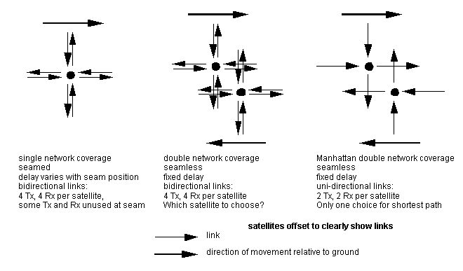
In assuming that each satellite communicates with all its neighbours by sending and receiving information directly, we are assuming a form of bi-directional Manhattan network. This gives us the double network coverage and seeing two planes of the network from the ground that wrapping a torus onto a sphere implies, along with the resulting redundancy.
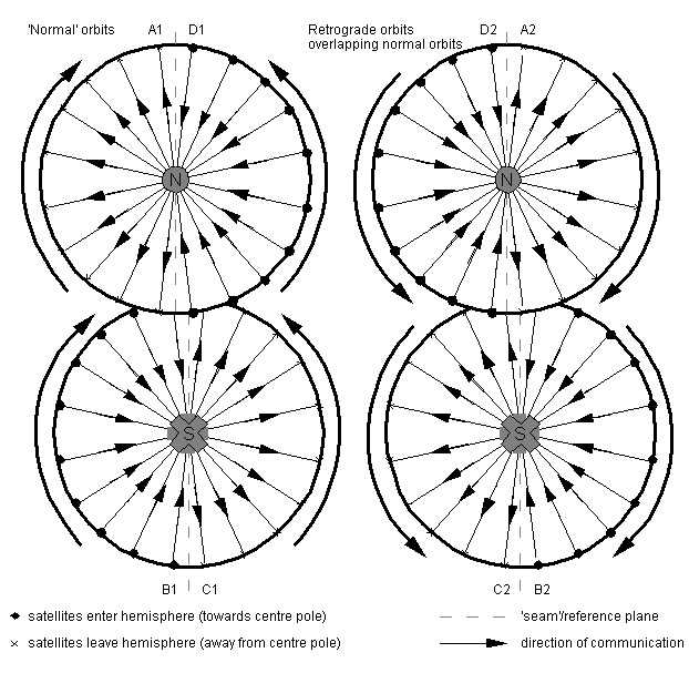
Figure 2.8: A seamless Manhattan satellite constellation
with fewer ISLs
However, this need not be the case. If we have double network coverage or bi-directional Manhattan, we have more links than we need to ensure full communication. By reducing the links to the Manhattan case, as shown in Figure 2.7, we still have a fully-connected constellation network, and the ground station chooses the satellite it wishes to send to depending on where it wants to communicate with in order to obtain the shortest route.
A full seamless Manhattan constellation is shown in Figure 2.8. This shows all hemispheres as viewed from the north pole. The southern hemispheres are inverted and viewed through the earth, as if the earth was made of glass, as indicated by the dots and crosses at the poles. This allows a satellite's path to be followed off the edge of one hemisphere by moving to the same position on the touching hemisphere, although this viewing approach means that forward-and-right in one hemisphere is seen as forward-and-left in the other, as we switch between viewing the satellite from above and below.
In both the normal (1) and retrograde (2) orbits, a satellite or node will travel between half-hemispheres in the order ABCDA, as will all communications in the same orbital plane. (in figure 2.7 we chose intraplane communications to be 'forwards' instead of 'backwards' relative to the satellites' movement over the ground. This is arbitrary.) With the Manhattan two Tx, two Rx satellites described in figure 2.6, communication between different planes over the seam can pass from hemisphere (1) to hemisphere (2) of the same letter or back. So, the 'normal' orbits in A1 pass packets round clockwise over the seam to A2, which pass them back to A1, following the arrows. (The bi-directional Manhattan network has bi-directional links and thus bi-directional arrows indicating that it can pass packets either clockwise or anticlockwise.)
Figure 2.9 Cross-section through the equator
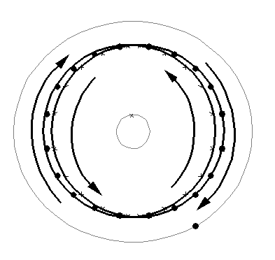
The seam is no longer really a seam, since communications pass over it due to the nature of double coverage. In fact, the seam is now simply a reference plane the orbits are placed relative to, and this reference plane can be at any longitude.
If we look at the equator and plot both normal and retrograde orbits' hemisphere entry/exit points, we can see the wrapped torus discussed in Figure 2.6 clearly. [Figure 2.9].
Seamless networks allow fixed-delay communication between two ground stations, as there is no seam changing position relative to the ground stations. The bi-directional Manhattan network, or double-network-coverage constellation, offers the ground station a choice of satellites for paths of the same delay length.
The Manhattan network, which has fewer links, offers the ground station the choice of a long path and a short path (not necessarily as short as in the bi-directional case) via different satellites in different network planes. However, for shortest-path communications between two ground stations, this means that a ground station must receive from one network plane and send to the other plane. (Overlap of spot beams of satellites travelling in different directions makes this difficult, but use of ground-fixed cells, as in Teledesic, should simplify the implementation.) Provided that delays of equal length both ways are not needed, only one overhead satellite can be used for both sending and receiving.
Manhattan networks are extensively discussed in computing literature [e.g. GoodGreen86, Maxemchuk87], and recognising that the satellite network constellation can be a bi-directional or unidirectional Manhattan network allows this literature to be applied in modelling the network performance.
The lack of redundancy in the Manhattan constellation network means that a single link failure can increase delay times considerably. This, coupled with the problems of technical implementation for satellite diversity, so that shortest network paths can be achieved by sending to one network layer and receiving from the other, makes implementing the Manhattan constellation network technically difficult.
The number of satellites that must be launched for a seamless network, and the problem of double network coverage, make building any form of seamless constellation network of little benefit unless fixed delay between ground stations is essential.
However, this does not invalidate the seamless network as a starting point for analysis, provided that we are aware of the limitations of the assumptions we make.
 ,
and the even spacing of the right angles of the ascending nodes
 1 ..
1 .. p
ensures full ground coverage. There is no coverage above a certain
latitude depending upon the size of
  ,
and to ensure that there is no break in the ground coverage below
that latitude it is necessary to add more orbital planes and adjust
orbital spacing until each direction wraps around to join itself,
giving the double network coverage discussed above.
The delta pattern can be thought of as equivalent to the double-coverage star, but for a narrower band of latitudes about the equator. Again, it would be possible for satellites travelling towards one pole to 'drop out' of the network, effectively giving the topology of a polar-axis single-coverage cylinder, or for the double-coverage delta pattern to be split into two single-coverage networks in this way.
The delta pattern with a very high inclination and the extra orbits
giving double network coverage removed is very similar to a star
pattern. For Iridium,  =86.4o,
and the problem of maintaining ISLs at high latitudes and high
relative velocities is simply avoided by having only three lines
of interplane ISLs around the equator, where the relative velocities
of satellites in different orbital planes are low, as detailed
in 3.3.2.1.
A seamless delta network gives double network coverage of each point on the ground under the network, leading to complex ground-space analysis or simply turning the satellites off for half the time, just as previously discussed for the double-network-coverage star network.
It would be possible to place our orbits with constant inclination to any reference plane, which does not have to be the equator. However, if we place the orbits with constant inclination to a plane other than the equator, we complicate the ground paths, and the varying action of precession due to the oblateness of the earth will act to distort the network, making controlling ground coverage and maintaining ISLs via pointing much more complex. As a result, the equator is the only reference plane we consider.
These are circular orbits of varying inclination  and spacing
  that attempt to distribute
orbital coverage in all dimensions. A large number of different
constellations are possible. However, varying inclinations result
in varying precessions due to the oblateness of the earth, making
it difficult to maintain relative orbital positions between orbital
planes and thus the network topology via ISLs.
Clare87 details the constellations where the satellites are placed at the vertices of Platonic solids centred on the earth to ensure even coverage (effectively a subset of the delta network with the addition of an equatorial orbit), provides diagrams showing orbital positions, and does some traffic analysis of the resulting ISL networks. The differential precession problem caused by varying inclination is avoided as all orbits are at the same inclination, with the exception of the equatorial orbit, which is completely unaffected by precession. However, the large angles between orbital planes for the simple Platonic solids (which must also be Archimedian solids for even ground coverage) make maintaining ISLs difficult, as satellites in neighbouring planes have large relative speeds with increased Doppler shifts, and pointing is difficult. The lack of precession of the equatorial orbit will cause equatorial satellites to fall out of sync with the other satellites.
Ballard80 concentrates on the bounds of multiple satellite visibility by interleaving low-inclination multiple planes containing few satellites and using careful phasing to fill in the gaps between satellite footprints in the same plane. This does not use the 'street of coverage' approach (required for near-polar constellations with near-parallel planes) that is assumed by Walker and detailed in Rider85. Although interleaving and careful phase alignment of planes for coverage is adopted by Globalstar to decrease the number of satellites required, it places severe constraints on inter-satellite networking, and we will not consider it further here.
Like the other constellation patterns outlined earlier, these orbital patterns will repeat at regular intervals, so analysis of a quasi-stationary constellation is possible. Despite their even ground coverage, these patterns pose difficulties for ISLs, with disadvantages that the delta and star configurations do not have. We will not examine these patterns further here.
Provided that we account for the effects of double network coverage, we can begin analysis with a seamless, truly homogeneous network where every satellite node is identical, sees the same network in the same way, and considers itself to be the centre of the network. This homogeneous network is a useful starting point for mathematical analysis, from which we can approach the much more likely seamed case with single coverage, provided we remember the differences between seamed and seamless networks and do not equate single and double network coverage.
Ignoring this dramatically simplifies the initial analysis. Once the initial analysis and accompanying simulation are built, we can build on them to introduce more complexity and better approximate realistic systems.
More importantly, we can see from the physical geometry that link distances vary around the earth and in different directions from the satellite. This is significant, and means that propagation delay should be one of the first 'realistic' factors to be introduced into the basic simulation to see if delay budgets are met and to consider how different routes can be favoured as the propagation delays are shorter.
At a more realistic level, variations in propagation delay will lead to difficulties in synchronisation and timing between satellites if it is desired to implement some form of SDH or ATM network. The propagation delay can also be used as a queue for short packets, which has interesting implications for a deflection-routing-based network.
However, we do not wish to be distracted by physical implementation until we have some initial network analysis, so this will be looked at later.
This ignores real considerations such as political, demographic and terrain influences on the choice of ground station location or the distinction between land and sea.
Mathematically, it is very convenient to assume one GS per satellite node (that is, if we are assuming single, rather than double, network coverage) and to ignore diversity issues such as a station seeing more than one neighbouring satellite and spreading traffic between visible nodes or a satellite seeing more than one station.
(It should be possible to prove that randomly selecting visible satellites for all stations, if all stations can randomly select the same number of neighbouring satellites, should not affect the analysis for a large enough network. Of course, in real life different latitudes will see different numbers of satellites as the distance between orbit tracks narrow, so that may not be useful. Investigating how randomly selecting one of a satellites' neighbours for sending/receiving traffic affects results, assuming that a GS can see all neighbours of the node 'connected' to it, would be a good starting point. It may be necessary to verify that the independence assumption for input and for through traffic still holds.)
We can assume that messages received from GSs follow the well-known Poisson arrival distribution for network traffic, just as they would for any other computer network. This is chosen solely as a starting point; distributions of different forms of traffic differ and are not necessarily Poisson.
This neglects a number of mobile issues, such as handover of mobile stations, the amount of mobile users active at any one time, capacity needed for tracking users and ringing handsets, and so on.
As we do for gateway stations, we will assume for convenience that the messages from the pool of mobile users related to a satellite follow the Poisson arrival distribution for network traffic.
In any such network, there will be a number of packet queues at each node, and packets from a queue will enter one or more other queues, merging with packets from other queues as they do so. This changes the character of the arrival processes at later (or 'downstream', as we are considering a flow of traffic) queues.
The state model of a single node with a queue, with Poisson arrivals, is well known, and can be represented with Markov chains (the well-known M/M/1 case). However, if we add a queue at a second node, which receives and then processes all the packets coming from this first queue, the second queue will not have Poisson arrivals, since queuing at the first node has changed the character of the traffic stream.
It is found that, after the first queue, the interarrival times become strongly correlated with the packet lengths. A long packet will take time to be processed at the first queue, with short packets behind it, but this processing time will allow the second queue to empty, so that the long packet is processed immediately as it enters the second queue. This is analogous to vehicles flowing along a busy street where overtaking is not possible. Our long packet is a slow bus, and there will be empty space in front of the bus (the second server) while faster cars (shorter packets) queue up behind the truck. Just as more cars will wait behind a bus as time goes by and the gap in front of the bus will increase, so the arrival rate at subsequent queues will change with time. (A neat analogy from 'Data Networks' section 3.6.)
In the case of a line of nodes passing packets of fixed length downstream, the interarrival time is constant and equal to the packet length, and there is no queuing as each packet is processed once it has arrived, and then the next packet, which arrived as that packet was processed, is ready for processing. Queuing is eliminated in this linear case.
However, the Kleinrock independence approximation states that merging independent traffic streams, as we are doing in our satellite constellation network, acts to restore the independence of interarrival times and average traffic length at the server, so that each 'downstream' node can be approximated by the well-known M/M/1 queue. As the correlation between interarrival times and packet lengths is removed, we can consider each node as an isolated M/M/1 queue again, making analysis much more tractable.
From this, we can see that input to the satellite from the ground, where we merge the independent traffic streams from the mobile users and the ground stations, will be M/M/1, by the same principle. However, this assumes that the streams are independent, which will not be the case as calls between mobiles and the terrestrial network - a very high proportion of traffic - will be routed up to the satellite and down to the ground station to the terrestrial network. So, if the ground station is very busy, the mobile users are very busy, and there may be some correlation, destroying the approximation for the satellite input. This can be dealt with by either:
It is likely that the satellite constellation network will have packets of fixed length, as this is extremely convenient for sharing between mobile users on combinations of time, frequency and coding division of available capacity. Considering fixed-length packets allows us to consider using ATM protocols for communication at a later stage.
If the network is very lightly loaded, the homogeneous nature of the network will act with the light load against the Kleinrock independence approximation, and there will be very little queuing of packets. Each packet will consist of header and content; if there is no queue, rather than waiting for an entire packet to arrive before processing it, processing the header on the fly and passing the packet on to its destination as it arrives is a good idea to decrease delay times through the network; the fixed packet length should make this easier to do. This is an important advantage, given the interactive nature of the constellation traffic and the related delay budgets that must be met for adequate performance.
This idea of increasing network throughput, when load is minimal, by processing arriving packets immediately if nothing is queuing already is called virtual cut-through switching (VCT), as introduced by KerKle79. VCT can be considered as approximating circuit switching when load is light and there is little queuing at nodes, and being identical to traditional packet switching when load is heavy, with long queues.
A node will have a number of connecting ISLs, or just links, to neighbouring nodes in the network. Traffic can pass either way between nodes connected via a link in this way. KleSil83 defines the degree of a node, N, to be the number of nodes in the network the node can communicate with, including itself. However, when we look at a network, we can easily count the number of connections to other nodes a node has. As in Wang94, let's call this number Nc, and then
Nc = N - 1
Since we are initially considering a homogeneous mesh network, N and Nc will have constant values for each node in the network.
Packets arriving and leaving a node via ISLs can considered to be within the constellation network. However, packets originating from the earth - either the associated ground station or the mobile users - are entering the network at this node. As far as the rest of the constellation network is concerned, the node is the source of these packets. Similarly, packets exiting the constellation network at a node to the ground station or mobile users leave the network at this node, and the network considers the node to sink these packets. During a two-way interactive connection sending packets across the network, there will be two nodes both sourcing and sinking packets entering and leaving the network.
We will ignore traffic generated at a node within the network, say for network control purposes, as this should be very small compared to the traffic travelling through the network from the earth. However, a node can act as both source and sink at once, in the case of mobile users communicating with the local ground station in the satellite footprint.
In graph theory terms, our satellite nodes, where links intersect, are described as vertices, where edges intersect. We are considering bi-directional communication, so that each line we draw on a graph of a network is really two links or edges in opposite directions between common vertices or nodes. This gives us a specific form of a digraph. We will adopt the notation of nodes (from computer networking) and links (from the satellite field) in the hope that these are more familiar to the reader.
Since we want ISLs between nodes, n must be sufficient to allow
line-of-sight communication between the nodes without blockage
by the earth. Each of the n nodes will communicate with the neighbouring
node ahead of it (the previous node relative to the ground) and
behind it (the next node relative to the ground), forming a ring
of communication in the ring of the orbit [Figure 3.2].
We can see that this is the case Nc = 2.
Figure 3.2: Single orbital plane
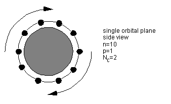
All of the nodes in the same orbit are on the same orbital plane, and we will call communication with nodes ahead and behind intraplane (within the plane) communication. For a circular orbit, this intraplane communication can be by fixed antennae or by optical link, as the nodes will always be in the same position relative to one another.
In the seamless case, each edge of the network (as opposed to the graph theory term edge for ISL) is connected to the opposing edge. The seamless equivalent of a seamed np network will have either S=2np satellites, or S = 2n(p-1) if a plane can be removed on becoming seamless. When seamless, the two contra-rotating planes that were either side of the seam now have their retrograde counterparts and do not need to be as close to ensure ground coverage. (This assumes that the phased-spacing 'streets of coverage' concept detailed in Rider85 is used. Teledesic has random phasing with fixed ground cells, and so does not need closer spacing around the seam, so it would not not need to adjust spacing when the constellation is altered to the seamless case.) As a result, all interplane spacing can be adjusted to the same street-of-coverage angle, and when the constellation is optimised a plane may be found redundant.
As discussed previously, a seamless np network is not physically
possible.
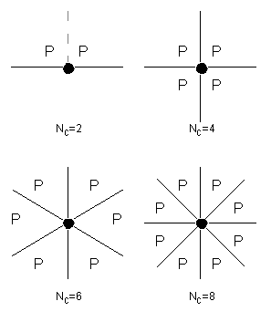
Figure 3.3: Repeating-pattern mesh networks

For the initial analysis of a seamless network, each node will have Nc links to neighbouring nodes. Nc will be at least 2, for complete communication when p=1, the case of the single orbital ring. The symmetrical cases of Nc = 2, 4, 6 and 8 are of interest to us, as these are multiple orbital planes with inter-plane links forming mesh networks [Figure 3.3].
Unlike the 2, 4 and 6 cases, Nc = 8 contains
links of significantly varying lengths between nodes(1: when all planes have the same phase). This, like variation in
inter-plane link length due to phase differences and spacing,
can be taken into account by considering propagation delay. From
a practical viewpoint, having to design your constellation so
as to make longer ISLs possible is likely to increase the number
of satellites needed, or to underuse the other ISLs.
For optimal ground coverage using Rider85's streets of coverage, there will be differences in phases between neighbouring planes in the grid. There are a number of different ways of staggering and connecting planes of different phases, which affect network diameter, inter-plane link length, and propagation delay. These will be looked at in depth in 3.4.
 = 86.4o
to the equator. Minimal eccentricity of 0.002 to ensure that satellites
do not collide at polar intersections.
66 active satellites consisting of 6 planes of 11 satellites per plane, or 6/11/2 in Walker notation. Originally designed as 7/11/2, hence the name, as Iridium is the element with atomic number 77 [Leopold91], but later revised to 66 satellites by removing a plane [FCC Authorization for Iridium]. (Dysprosium is the element with atomic number 66, and its Latin root means 'bad approach'. The name has not been changed.) There are also up to twelve additional spare satellites, two per plane, presumably to be kept in a higher parking orbit and dropped in to replace failed satellites.
Each satellite or node is capable of six links, comprising two intraplane forward and back, and two to satellites in each neighbouring plane. [FCC application for Iridium, p51] However, only four links are said to be active at any time. [GiuQuag95] Due to relative velocities and Doppler shift, there are only three lines of interplane ISLs near the equator. Division by the seam means that only six of the eleven satellites in each plane are involved in inter-plane ISLs, in two groups of three around the equator. Only twenty-four of the thirty-six satellites involved in ISLs will be fully four-connected at any time, again due to the seam; the topology is shown in Figure 3.4.
Figure 3.4: Network topology of Iridium
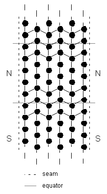
Iridium does have the potential to be sixway-connected, but available literature is unclear on the topology and reasons for the fourway restriction, and concentrates on the ground/space interface.
With this topology, a model for Iridium will lie somewhere between (6,6) and (6,11) fully-connected fourway rings.
A circuit-switching approach is taken; there are similarities to GSM in the ground/space interface.
An example ground path of an Iridium satellite is given in A2.1.1. Network has an estimated construction cost of US$3.8 billion.
 = 98.142
to 98.182o to the equator. Minimal
eccentricity of 0.00118 to ensure that satellites do not collide
at polar intersections.
840 active satellites consisting of 21 planes of 40 satellites per plane with random phasing between planes, or 21/40/random in Walker notation. There are also 84 additional spare satellites, or four per plane. [LawTuck94]
Each satellite or node is capable of eight links in four directions, to the nearest two satellites in each direction [Figure 3.5]. So each satellite communicates with its immediate intra- and interplane neighbours, and with the satellites beyond them to provide a degree of redundancy. (Figure 5 of LawTuck94 makes an excellent job of confusing the reader, but other sources confirm this layout.) This connectivity and resulting topology may be an artifact of satellite spacing, as the satellite network is described as fault tolerant and self-configuring, possibly as a result of its original military design.
Figure 3.5: How each Teledesic node sees its immediate
neighbours
Note the random phasing between planes.
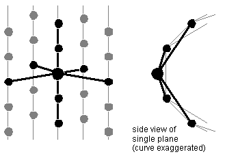
Limitations on interplane ISLs are not described in available literature. However, the large number of planes and close spacing results in low relative velocities and low Doppler shift, allowing connections near to the poles. We can therefore assume that Teledesic constitutes a fully-connected (21, 40) fourway ring, with additional links connecting each node to its second neighbours, at any time.
The network is described as using fast packet switching that is based on ATM developments. [Sturza95] Each packet can be routed along separate routes, and links can be selected on the basis of delay. [Satellite system patent application]
An example ground path of an Teledesic satellite is given in A2.1.2. Network has an estimated construction cost of US$9.6 billion.
This number of minimum paths in the grid can be found by superimposing Pascal's triangle upon the grid. As we move out from the source node across the grid, we can sum the number of ways to get to an intermediate node, which is the number of distinct minimum paths to that node, as the sum of the number of ways we got to nodes neighbouring that node. This simple summation builds up Pascal's triangle, which shows us that there are more minimum paths, and thus more traffic, passing through the centre of the grid [Figure 3.6].
At each point in Pascal's triangle, the number of paths you can take from the topmost node to a destination node is given by the sum of the numbers of paths to the last nodes you could have passed through on your way down.
Figure 3.6: Pascal's triangle for minimum paths
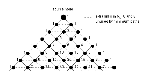
This applies to the cases Nc = 2 (although analysing a one-dimensional grid in this way is overkill, since you simply travel down one edge of Pascal's triangle and are forever 1-1-1-1), and the cases Nc = 4, 6 and 8, where Nc Pascal's triangles are joined edge-to-edge around the node of interest [Figure 3.7].
Figure 3.7: Mapping Pascal's triangle around
the source node
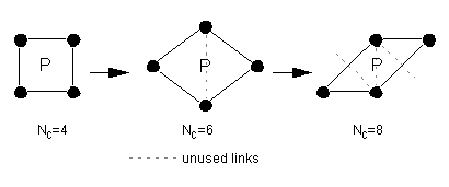
In the cases of Nc = 6 and 8 we are actually
viewing a sheared grid of squares, and the additional links in
these cases point away from the sink node and cannot form part
of a minimum path. These extra links are shown in Figure 3.6;
the only difference between the sixway and eightway cases is the
acuteness of the triangle. The shearing and rotation of the gridded
Pascal's triangle needed to get the sixway and eightway cases
is shown more clearly below [Figure 3.8].
Figure 3.8: Shearing the Pascal's grid
To maintain the same plane orientation, necessary rotation
of the sixway case is included here.
Pascal's triangle, and thus the number of minimum paths Np between two nodes, is generated by the formula:
![Np = [(x + y)!]/[x!y!]](eq1.gif)
where we travel x links from the source node in one direction, and y links in the orthogonal direction, down to the sink node. (Given in Wang95 without explanation.)
For Nc = 3, symmetry is lost, and Pascal's triangle does not apply.
Shapes of paths of a set length can be defined by passing through
a constraining anchor node, where the node is fixed in both space
and on the path so that that all the shapes of the path are split
into two distinct sections of fixed lengths. Alternatively, the
node can be unconstraining, where the anchoring node is fixed
in space but the path can slide through the node and the lengths
of the sections either side of the node are not fixed.
In the rectangular grid, we have two constraining anchors at opposing corners of the grid, and shapes of paths of fixed length between them.
These concepts will be useful to us in later analysis in 5.0.
D = DAB = x + y
and the number of paths of individual shape between A and B is given by

The grid will contain a total of x(y+1)+y(x+1) links and (x+1)(y+1) nodes.
On a complete mesh network of any shape, we can define the network diameter d of the mesh network to be the longest minimum path between constraining nodes, i.e. the length of the minimum paths between the nodes furthest away from each other, or the minimum distance communication in the network to ensure full intra-network communication between all nodes. In the case of a seamless mesh made by joining the edges of a grid, where edge wraps to opposing edge, d is different from and smaller than D. (Note that this notation differs from Wang94. As the diameter is the general case for a mesh network and will be smaller than the specific case of the grid encompassing the furthest points on that network, having d<D seems more logical.)
The word diameter is very handy, as here the furthest point away from a node above the earth will be the node halfway around the earth, at the opposite end of the diameter passing through the earth's centre. However, the name is applied to this distance in all networks, and can often be found in papers addressing the communications structures of parallel computers, such as hypercubes. In these structures, as in our seamless mesh, d is constant for every node in the network.
Just as D varies for different grids, we can see that d varies for different networks with different topologies. For an np seamless mesh, d varies depending upon the number of links Nc (3, 4, 6 or 8) and upon the phase differences between adjacent planes.
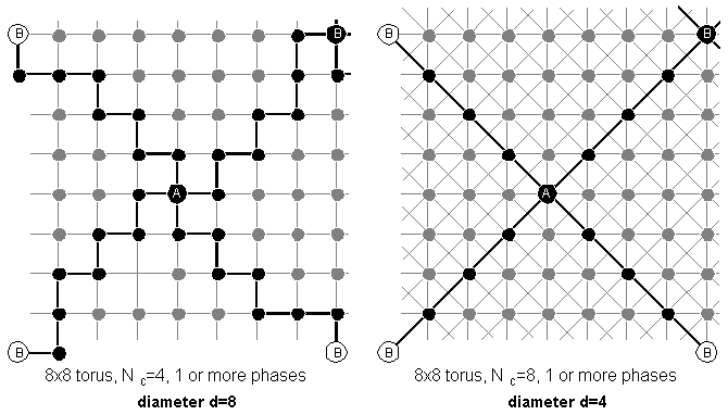
For example, let's consider an 8 by 8 seamless mesh and the various connection possibilities for that mesh, as shown in Figure 3.9. (For a satellite network to be seamless in this way we are assuming double network coverage of every point on the ground, so this is not directly analogous to a 'real' ISL network.)
When Nc = 4 we do not need to consider phase angle, as we always have a grid. However, when Nc is another value, phase angle and the number of planes affect the structure. We can see from Figure 3.9 that increasing the number of phases both reduces the network diameter and changes the number of different ways we can travel between two nodes.
Figure 3.9: Determining network diameter
3.9a Fourway and eightway connectivity
The greater connectivity provided by eightway connectivity halves
the network diameter.
The diameter for the threeway cases is the same as for the fourway cases, but is accomplished with less connectivity and fewer links. This may make sense from a cost viewpoint, where you have fewer, higher bandwidth, links for the same throughput.
The non-symmetrical Nc = 3 threeway case can be designed with all links the same length to avoid extra adjustment in propagation delay, but with phase staggering for optimal ground coverage this offsets its main advantage over an identical constellation with Nc=4 - taking the same number of links to get anywhere, but requiring less connections to do so. Wang94 attempts to discuss Nc = 3 in depth. As the threeway case does not use true rectangular grids and Pascal's triangle can not be used on it to count minimum paths, we will not consider it further here.
The sixway case falls between the fourway and eightway cases in both connectivity and diameter. The diameter of the sixway case can be decreased by going from two to three phases.
From these examples, we can see that, in general, the greater the network connectivity, the smaller the diameter to reach every point in the network. This is not a linear relationship.
 , and in a homogeneous
network
  will be the same for each
node.
In our satellite network, we can break  down into its components:
Let  t be the rate
of arrival of packets in transit from the rest of the network
at the node
Let  g be the rate
of arrival of packets from the ground users associated with that
satellite node.
 =
= t+
t+ g
g
Similarly, we can break down  g
into its components:
Let  b be the rate
of arrival of packets at the node from the gateway station, or
base.
Let  m be the rate
of arrival of packets at the node from the mobile users
 g=
g= b+
b+ m
m
In a non-ISL satellite constellation  t
=0, and
  m and
m and
 b are the same
and not independent as all mobile traffic is passed to the local
gateway in the satellite footprint. When ISLs are introduced,
 t can be non-zero,
and mobile-to-gateway traffic does not have to be to a local gateway
- in fact, there may not even be a local gateway,
and
  b can be zero.
In the case of a long-distance call to the terrestrial network,
traffic can be routed via ISLs to a gateway that is near or local
to the terrestrial party, to maximise use of the satellite network
and minimise terrestrial charges from the terrestrial networks.
(This is the concept referred to by BöttWer95 as ARS,
or Advanced Routing Strategy). It is therefore reasonable to assume
that
  b and
b and  m
are independent.
In accordance with the notation used in DoRaShi91, we can break the traffic arriving at the node down into categories depending on the distance, in terms of links, that the traffic still has to travel. All the traffic that has n remaining links to travel can be given the suffix n, where n is a natural number. It is convenient to consider all the traffic that has n or more links left to travel, too - this can be shown by giving it the suffix n+.
From this

and we can apply this similarly to each of the subcategories of
 defined above, substituting
  t
etc. for
  .
.

and we can again substitute all the subcategories of  for
for  .
.
We can visualise this by thinking of a node as lying at the centre of circles of nodes, where the radius of each circle is the number of links needed to reach the nodes lying on the circumference of that circle [Figure 4.1]. The circles are of radius k links, where k is a positive integer. Each circle will have kNc nodes lying on it, where k is the radius of that circle.
Figure 4.1:  kand
kand  k+
shown graphically
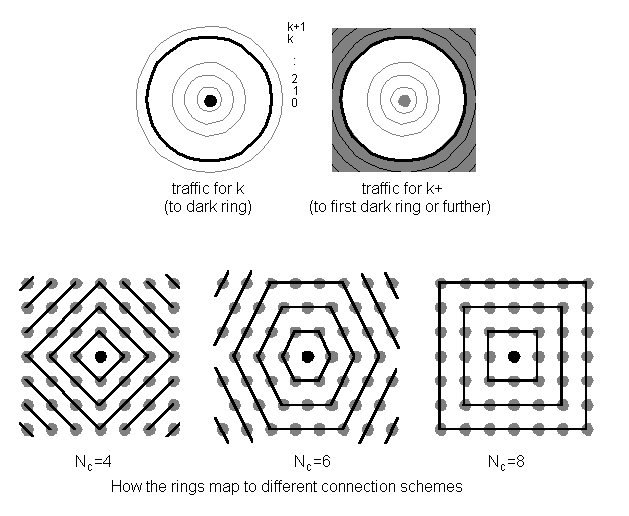
We can represent  k
(and the subcategories of
  ) as the
rate of traffic arriving at the central node, bound to travel
k more links along minimum paths to the kth concentric circle.
Similarly,
  k+
and its subcategories represent the rate of traffic arriving at
the central node, bound to travel k or more links along minimum
paths to the kth concentric circle or further. We can represent
these graphically.
So in a homogeneous network, the rate of traffic coming from the
ground,  g, is
split so that each of the outgoing links to the Nc
neighbours has rate

travelling over it. Similarly, the rate of traffic coming from
the rest of the network over the Nc connecting
links totals  t.
In a homogeneous network, the rate of traffic coming in over each
link will be

[If this seems counterintuitive, a simple proof is given in Appendix A1.2]
In the network, we will neglect  g0
as that is self-traffic that does not enter the network.
However,
  t0
is the rate of traffic arriving from the network and leaving at
the node of interest, and is significant to the network if we
are not considering VCT.
Let the grids be AB and BC, of size (xAB,yAB) and (xBC,yBC), and let them lie inside the larger grid AC, of size (xAC,yAC) [Figure 5.1].
Figure 5.1: Minimum paths through a node as the multiples
of two grids
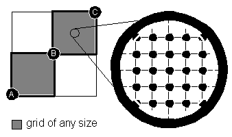
We know the distances of the grids, where the distance is the number of links that must be taken to cross from corner to opposing corner:
DAB = xAB + yAB
DBC = xBC + yBC

The number of minimum paths from A to B in grid AB is given by:

and similarly for grid BC:

and the total number of minimum paths between A and C that pass through B is given by
![PABC = PAB.PBC = [DAB!DBC!]/[xAB!yAB!xBC!yBC!]](eq10.gif)
The total number of minimum paths between A and C is given by

so the proportion of traffic between A and C that passes through B is

If B fails, this proportion of traffic will need to be re-routed.
From this, if we say that we want all the minimum paths between A and C that flow through B and a second node Z that we place between B and C, the total number of minimum paths passing between A and C that pass through both B and Z is given by
![PABZC = PAB.PBZ.PZC = DAB!DBZ!DZD!/[xAB!yAB!xBZ!yBZ!xZD!yZD!]](eq13.gif)
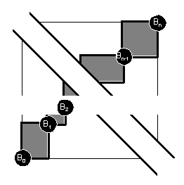
We can generalise from this: how many minimum paths are there from A to C that pass through an intermediate series of n fixed points B1..Bn? For mathematical convenience, the point C is also denoted Bn+1 and the point A is B0. Each of the n fixed points lies at the opposite corner of a grid from the previous fixed point. Each grid Bk-1 to Bk is of size (xk,yk), where k varies between 1 and n+1. So the number of minimum paths between A and C that pass through all the intermediate points B1..Bn is given by:

and these grids must touch corner-to-corner forming a 'staircase' pattern, otherwise the paths are not minimums [Figure 5.2].
Figure 5.2: Minimum paths through multiple fixed points

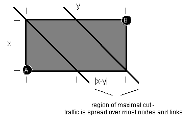
sets of links [Figure 5.3]. In a homogeneous grid, the rate of traffic between A to B on these links will be at an average minimum
![(lambda-subscript-AB + lambda-subscript-BA)/[smaller(x,y) + 1]](eq16.gif)
across these nodes.
Figure 5.3: Maximal cut across a grid
The cases of the centre node in the diagram, or node of interest, sourcing or sinking traffic is given by reducing the size of either of the two grids to (0,0) and reversing path flow to cover all orientations.
Figure 5.4: Counting minimum paths and traffic through
a node by rotational symmetry
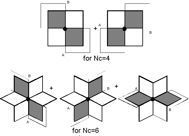
As the anchoring node is an unconstraining node, it can lie at any point on the minimum path. As the minimum path is k links long there are k+1 possible positions for the node of interest, and moving the node of interest along the minimum path in this way allows the minimum path to cover both parallelograms in the bow tie. This results in an overall shape slightly different from the bow tie drawn above, where the minimum path reaches further at the rotation edges (maximum radius k, when the node is a sink or source) and less in the middle; the circular shape shown in Figure 4.1, in fact.
The bow tie defined by the central node and end points of the minimum path at any one time is simply an instance between any two chosen constraining anchor points, the source and sink nodes, within the boundaries of this area, whose shapes pass through the unconstraining node of interest. The unconstraining node can be superimposed on the constraining source or sink node.
Each link in the minimum path can be in one of two directions. We can define the distances of the two grids of the bow tie defined by this path to be lengths n and (k-n), where n varies depending upon the position of the node of interest. The total number of distinct shapes of the constrained minimum path through the bow tie is:

Of those shapes, only two will be perfectly straight, but in orthogonal directions, and we wish to remove one as the other will overlap it by later rotation to the positions of other bow-ties. That gives us 2k-1 minimum paths for each position of the node of interest along the k-length minimum path.
There are  rotations of the bow tie to
cover all paths through the node of interest.
For two-way communication, each end of the path can be source or sink, doubling the number of paths.
From this, we can see that the number of minimum paths of length k passing through the node of interest is:

On a seamless mesh of network diameter d, the number of minimum paths through any node can be given by:
![Nc[the sum of k is 1 to d of (k+1)(2^k-1)]](eq19.gif) paths
paths
Unfortunately, this formula is only useful for seamless (torus) meshes generated from wrapping square grids. The much more likely seamed or even rectangular seamless toroidal meshes are not adequately dealt with by this analysis.
Of these minimum paths, the number of minimum paths where the central node is a source equals the number of minimum paths when it is a sink, in one of the k+1 possible positions for the node, at the end. This number is:

and for the seamless mesh the number of minimum paths sourced or sunk by a node is given by:
![Nc[the sum of k is 1 to d of (2^k-1)]](eq21.gif) paths
paths
If the node of interest is an end-point (source or sink), then
it is communicating with a circle of Nck nodes
lying the circle radius of k links away. Each of the nodes on
this circle will sink or source an average of:

paths.
Similarly, the number of nodes communicating with nodes distance k links away from them, whose minimum paths pass through the unconstraining anchor node of interest, is given by the sum of the circles around the node of interest to the maximum circle radius k.
![Nc[the sum of j is 1 to k of j] = Nck(1+k)/2](eq23.gif)
paths. On average, each node sinks or sources:
![[2(Nc/2)(k+1)(2^k-1)]/[Nck(1+k)/2] = 2(2^k-1)/k](eq24.gif)
which is twice as much as previously. However, this is averaging over an area rather than a perimeter, and does not appear useful when considering a traffic function relating to distance travelled.
In a homogeneous infinite mesh, the further away a destination node is, the more possible shapes of constrained minimum paths there are to choose from to travel there, and the less traffic there is that will travel along each shape. Distance away from a node and average number of paths to a node a distance away from source will be useful to us.
Figure 5.5: Node of interest on the corner of a semi-infinite
grid
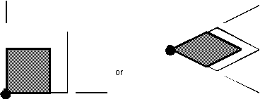
The number of minimum paths of length k sourced from the corner of a grid is 2k. We must multiply the number of paths by 2 for both sinking and sourcing, giving us

minimum paths of length k.
This node is also an intermediate unconstraining node for through paths that are constrained by source and sink anchor nodes that lie on different edges of the whole grid [Figure 5.6]. Two minimum paths pass through the corner node for each pair of edge nodes, chosen one from each edge.
For a minimum path of length k (forming a right angle with the corner at our node of interest on the corner of the semi-infinite grid), there will be (k-1) possible positions as the path slides from 1 link/node/(k-1) links to (k-1) links/node/1 link along each edge/edge of the network. We will split the minimum path into n links and (k-n) links along each edge.
Figure 5.6: Through paths on the corner

Doubling for sourcing and sinking, that gives
2(k-1) through paths at our corner node.
The total number of minimum paths of length k associated with the corner node is thus

So on an infinite grid the total number of paths associated with the corner node is
![2[the sum of k is 1 to infinity of (2^k + k -1)]](eq27.gif) paths.
paths.
This result is of little practical use, but tells us how the number of paths rises to infinity as we move further away from the corner node.
We can see that the node of interest sinks and sources
![[2^k + (2^k - 1)]2 = 2[2^(k+1) - 1]](eq28.gif)
minimum paths of length k, having subtracted one instance of a path making up the boundary between the two regions.
Figure 5.7: Node on the edge of a semi-infinite plane
(two joined semi-infinite grids)
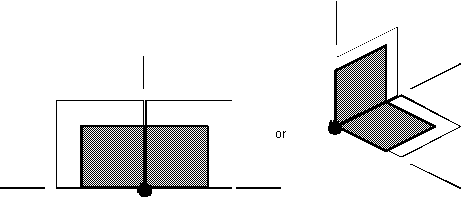
There are also through paths of the form of a grid on one side of the node and a straight line along the edge on the other [Figure 5.9]. These through paths can vary in length from one edge link on one side of the node with a flexible minimum path of length (k-1) links anchored at the node on the other, to (k-1) edge links on one side of the node and a flexible path of one link on the other. Mirroring and subtraction of common paths must be taken into account.
Figure 5.8: Minimum paths passing through a node on
the edge
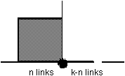
Let the number of edge links, where movement of the minimum path is constrained, be (k-n). That leaves us n links with the 2n degrees of freedom accorded a minimum path.
The mirror of this will have the n links straight along the edge in common with the original, and we must subtract these. The number of minimum paths passing through the node, but not being sunk or sourced by the node, is:
![2[the sum of n is 1 to (k-1) of (2^n +2^n - 1)] = 2[the sum of n is 1 to (k-1) of (2^(n+1) - 1)]](eq29.gif)
So the total number of unconstrained minimum paths of length k passing through this anchoring node, which includes paths sunk and sourced by the node, is:
![2(2^(k+1) - 1) + 2[the sum of n is 1 to (k-1) of (2^(n+1) -1)] = 2[the sum of n is 1 to k of (2^(n+1) - 1)]](eq30.gif)
and on an infinite plane the total number of minimum paths passing through the node is
![2[the sum of k is 1 to infinity of [the sum of n is 1 to k of (2^(n+1) - 1)]]](eq31.gif) paths
paths
Programs were written in Matlab to count the number of minimum paths in grids, rings and toruses of varying size and connectivity. Matlab operates upon matrices, so Nc=4 and 8 can be considered relatively easily. We know that results for a sixway grid will fall between the results for a fourway and eightway grid.
Wrapping the network one way, to form a uniform cylinder, decreases the diameter and thus the size of the maximum grid. This, in turn, reduces the overall number of paths each node sources and sinks, although central nodes may see a slight rise since it is often possible to go more than one way to a node across the ring. Similarly, wrapping the network the other way to form a torus reduces the number of paths sourced and sunk still further, again with a slight change in the middle.
This is illustrated graphically for a (6,11,4) node network - a fourway-connected rectangular 6 by 11 grid of nodes [Figure 5.9]. This size was chosen as the ring case is approximate to Iridium, although the currently proposed model for Iridium has fewer crosslinks, having only six lines of interplane links (three equatorial lines broken by the seam) instead of eleven. [Pathwise, Iridium as currently suggested for implementation will lie between (6,6) and (6,11) as detailed in 3.3.2.1]
Figure 5.9: Comparison of sources /sinks for fourway
grid, ring and torus
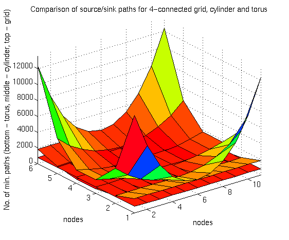
The number of sources or sinks is shown; to sum them, simply double the figures. Increased connectivity introduces more edges of Pascal's triangles and slows the increase in minimum paths with distance to reduce the number of minimum paths in the grid, as a comparison of fourway and eightway (6,11) grids shows [Figure 5.10].
Figure 5.10: Comparison of source/sink fourway and
eightway connectivity for a grid
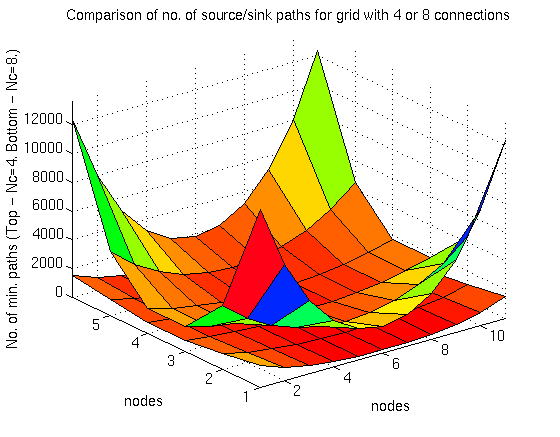
Figure 5.11: Comparison of all-path and source+sink
totals for a fourway grid
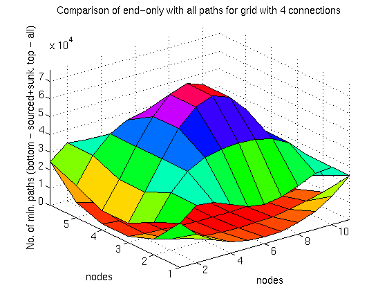
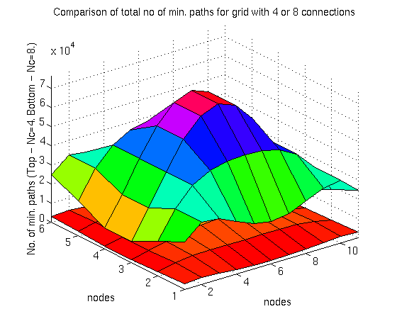
The higher connectivity of the eightway grid means that the total number of minimum paths to consider is also much less than in the fourway case [Figure 5.12]. Here, the not-computed sixway case will fall between these two curves, with the same order of magnitude of possible minimum paths.
Figure 5.12: Comparison of all-path totals for fourway
and eightway grids
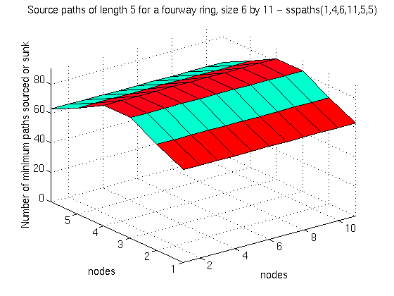
For example, we can calculate the number of paths of length five hops sourced or sunk by each node in a large Iridium-sized ring network [Figure 5.13].
Figure 5.13: Sourced/sunk paths of length 5 hops in
an Iridium-sized ring network
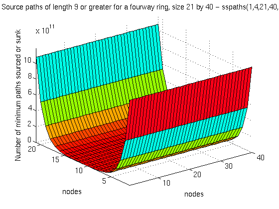
We can also request the number of k+ paths going k hops or further, such as paths of 9 hops or greater in a Teledesic-sized fourway-connected network [Figure 5.14].
Figure 5.14: Paths of length 9+ hops in a Teledesic-sized
fourway-connected ring network
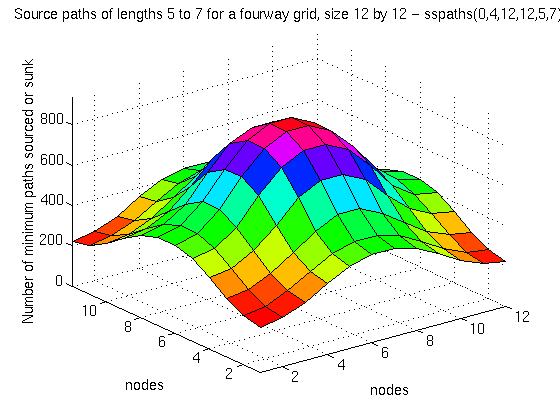
And we can request any set of paths, such as paths of length 5 to 7 in a square 12 by 12 grid [Figure 5.15].
Figure 5.15: Paths of length 5 to 7 hops in a square
12 by 12 grid
The number of possible minimum-path routes across the network will also vary with the seam's position. We can obtain a measure of this by breaking down all of the source paths from a node by path length, and comparing them to the total number of paths for that node.
For a multimedia application, there may be a (small) maximum allowable delay, which we can express in terms of a maximum number of links or hops that a minimum path can take between the two communicating ground stations - paths of this length or less are satisfactory.
By comparing the number of satisfactory paths to the total number of possible paths, we can characterise different networks. As the seam position varies, the amount of possible paths available will fluctuate between a minimum and a maximum; the minimum, as a proportion of the total number of paths available, is the figure of interest to us as an indication of guarantee of service.
The connectivity of fourway and eightway networks of the same size were compared by graphing the fraction of 'acceptable' paths for a given maximum-delay/maximum no. of links or hops requirement.
An eightway Iridium-sized (6,11) ring network has a higher fraction of acceptable paths for a given hop limit than its fourway equivalent [Figure 5.16]. Similarly, an eightway Teledesic-sized (21, 40) ring network has a consistently higher fraction of acceptable paths for a given hop limit that its fourway case [Figure 5.17]. In both cases, the sixway cases can be expected to lie between the fourway and eightway lines, giving us a measure of sixway performance without having to actually do the sixway calculations.
Figure 5.16: Delay profile of an Iridium-sized
ring network
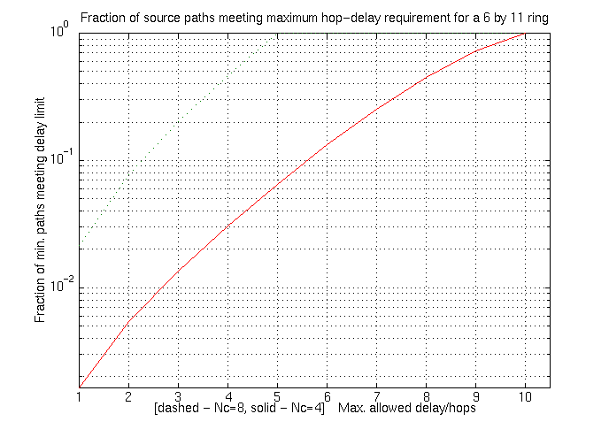
Figure 5.17: Delay profile of a Teledesic-sized
ring network
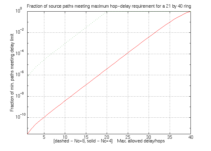
Any size ring network is wrapped around the same earth with the same ground stations, so it should be possible to compare networks of different sizes using this measure. This was done by considering the maximum distance in hops of a given network. (The term diameter is not used, as the diameter of the network is not the same for each node in the network).
The maximum distance in hops for any size network maps to the same distance between ground stations on the earth, and (approximately) the same distance in orbital hob propagation time, assuming networks of the same altitude - Teledesic and Iridium are of similar altitudes. So, by expressing hop distance as a fraction of maximum distance, it should be possible to compare networks of different sizes.
Figure 5.18 does this, showing, from top left to bottom right, eightway and fourway curves for the small (6,6) Iridium-sized network, the large (6,11) Iridium-sized network, and (21,40) Teledesic-sized network.
A measure of the 'real' Iridium network should lie between the (6,6) and (6,11) fourway cases, as discussed in 3.3.2.1. A measure of the 'real' Teledesic, with its eight links in four directions as discussed in 3.3.2.2, should lie around the fourway and eightway cases plotted. (Intuition suggests nearer the eightway case.)
The graph suggests that, for multimedia applications where maximum delay is of importance, a large, eightway-connected network may offer better performance than a smaller fourway-connected network, all other network characteristics being equal.
While this is a gross oversimplification of any comparison between Iridium and Teledesic, which have very different aims, technologies, ISL capacities and so on, this comparison technique may be useful as an indication in selecting the size and connectivity of a wrapped grid or seamed-ring network when low-delay circuit-switched connections are desired.
Figure 5.18: Comparing Iridium- and Teledesic-sized
ring networks
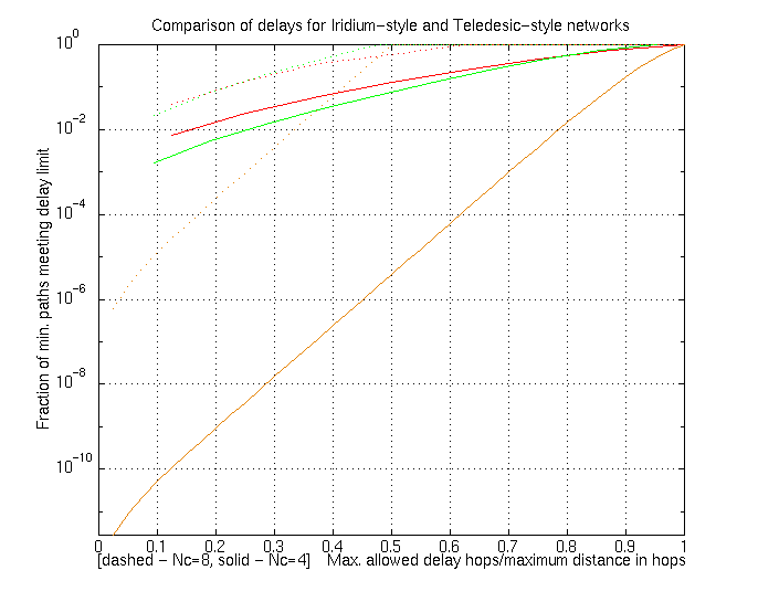
Generalising equations for different values of Nc would be very useful.
The Nc = 8 and 3 cases can be dealt with here as examples of weighting on weighting for their link lengths.
Intuition suggests a model that switches between large use of longitudinal intra-plane links when the seam lies across the busy spot, and more use of intra-plane links when the busy spot is in the centre of the network, but this has not been confirmed.
The Manhattan constellation network offers constant delays and cheaper satellites with less communication equipment onboard, but poses problems of diversity.
This might be a useful approach for the future networking of initially non-ISL-networked rosette constellations, whose interleaved ground coverage would disrupt 'normal' intraplane network constellation satellite-satellite handover.
This work has been more difficult than expected, due to the lack
of good prior work in the field, and this has prevented the early
creation of realistic simulations. However, the characteristics
of the constellation network have been investigated in depth,
and the resulting concepts of single and double network coverage,
and their effects on seamlessness, appear to be novel and not
discussed in prior literature.
From this work, we can conclude that seamed constellation networks
possess the property of single network coverage and offer their
users connections of highly variable delay, where the delay encountered
depends upon the relative locations of the communicating stations
and of the seam.
Seamless constellation networks possess the property of double network coverage and offer their users relatively fixed delays, where the delay encountered depends only upon the relative locations of the communicating stations.
FCC Order and authorization concerning the above, 31 January 1995.
Focuses on Motorola's Iridium proposal. Available on the world-wide web (WWW) at:
Focuses on the McCaw/Calling Teledesic proposal. Available on the world-wide web (WWW) at:
http://www.seas.upenn.edu/˜gaj1/ethergg.html
One of a series of essays making up in Telecosm, available from:

ignoring the change of the speed of light in atmosphere, which is insignificant compared to the total distance. Thus a round trip has a minimum associated delay of twice that, or 239 milliseconds. For ground stations not at the satellite's nadir, the delay will be slightly larger, giving the average often-quoted round-trip time of 250 milliseconds.

Here the change of speed of light in atmosphere is more significant; as the footprints of LEOs are smaller, increase in delay across the much smaller footprint is far less. A round-trip delay is often quoted as being under 10 milliseconds.
 t,
then the rate of traffic going outwards to the neighbouring nodes
must also be
  t.
If each neighbour contributes

each neighbour must also receive that amount, even if traffic from a node can only be sent to n other nodes, where n < Nc.
Here, packets will not be sent back to the node they came from, so each packet can go to one of (Nc - 1) Each link can divide the

it provides among the (Nc - 1) other neighbouring nodes, since packets are not going to travel back to the node they just came from, but in the homogeneous case will be spread evenly to all other nodes. So each neighbouring node receives traffic at rate
![lambda-subscript-t/[Nc(Nc-1)]](eq34.gif)
from each of the (Nc-1) other nodes, since
it can't receive traffic from itself. The total traffic going
out over each connecting link to each neighbouring node is thus
![lambda-subscript-t(Nc-1)/[Nc(Nc-1)]](eq35.gif)
The common terms cancel, and we are left with

or what came in over that link, which makes sense since this is homogeneous and conservation of flow (via Kirchoff's laws) must be preserved. This, summed with the ground input and considering VCT, is effectively given in DoRaShi91, theorem 1; Wang95 does not think about the distribution among (Nc - 1) other nodes correctly, and as a result Wang95 equation (1) and everything depending on it is in error.
Note that Teledesic uses retrograde orbits, so that the ground tracks of its satellites travel westwards, while those of the Iridium constellation travel eastwards.
Figure A2.1: Ground track of a typical satellite in
the Iridium constellation
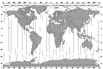
Figure A2.2: Ground track of a typical satellite in
the Teledesic constellation
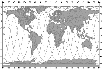
This was done for the fourway and eightway connectivities that map easily onto a rectangular matrix. The performance of sixway connectivity will lie between the fourway and eightway bounds.
Initial versions were written and then accelerated to take advantage of the topology. For example, for a torus you only need to perform calculations for a single node, since all nodes are identical, and you can just copy the results of one node to all the other node. However, such shortcuts were only undertaken once results had been generated slowly, to provide verification of the worth of the acceleration methods.
Initial source/sink counting routines for grid, ring and torus were combined into one single command, for networks of any degree of wrapping, that also generated counts of paths of a given set of lengths, so that traffic could be broken down in terms of path length. The program for this command takes advantage of topology to accelerate the calculations - important for large constellations - and can generate results for fourway and eightway meshes. Results are calculated by sspaths() [A3.4.1] and shown by ssdisplay() [A3.4.2].
The number of paths available to meet a given delay parameter
is calculated by delayresults() [A3.5.1], and graphed
by displaydelay() [A3.5.2]. The delay profiles of
Iridium- and Teledesic-size networks are calculated by comparedelay()
[A3.5.3].
Other programs producing graphs from the calculated path matrices, as seen in the body of the report, are given in A3.6.
In order to calculate minimum paths, a Pascal's (for four-way connections) or double-Pascal's (for eightway connections) triangle is required for a lookup table.
Initially, numbers of minimum paths were generated when needed using the factorial function factorial(number) [A3.1.1]. This was then replaced by the faster Pascal's lookup table, used in fourway(size) [A3.1.2]. A routine was needed to provide a similar double-Pascal lookup table for eightway grids, and eightway(size) was written [A3.1.3].
function [result] = factorial(x)
%           FACTORIAL(x) returns x!
%           where x! is x*(x-1)*(x-2)*..*1

% Copyright (C) Lloyd Wood, 3 August 1995.
% Written at TELECOM Paris Site de Toulouse
% For MSc project, University of Surrey

% I can't BELIEVE that matlab doesn't know about factorials!
% still, this is pretty trivial to write...
% Only provides factorials for up to 170! on available suns
% Returns infinity for larger given numbers

% trap for given number being negative or not an integer
% (and return Not a Number if this is the case)
% before performing factorial calculation

if (x < 0)|(x ~= fix(x))|(x ~= real(x))
   result = NaN;
else
   result = x;
   for z = 1:x-1
      result = result*z;
   end
end

% trap for 0! = 1

if x == 0
   result = 1;
end
function [X] = fourway(size)


% FOURWAY   fourway-connectivity matrix generator
function for matlab

%           FOURWAY(size) returns square matrix of
that size


% Copyright (C) Lloyd Wood, 8 August 1995.

% Written at TELECOM Paris Site de Toulouse

% For MSc project, University of Surrey


% Returns a 'fourway' matrix for Nc=4. Simply a Pascal's

% triangle, so we map through to the Pascal's triangle
function.


X = pascal(size);
function [X] = eightway(size)


% EIGHTWAY  eightway-connectivity matrix generator
function for matlab

%           EIGHTWAY(size) returns square matrix
of that size


% Copyright (C) Lloyd Wood, 8 August 1995.

% Written at TELECOM Paris Site de Toulouse

% For MSc project, University of Surrey


% Returns an 'eightway' matrix for Nc=8. Similar
to a Pascal's

% triangle for Nc=4, but is actually two Pascal's
triangles in

% each 45-degree triangle, sharing the middle diagonal
of 1s.


% Create our matrix


X = eye(size);


for m = 1:size

   X(1,m) = 1;

end


% Create Pascal's triangle in one half of the matrix


if (size>2)

   for n = 3:size

      for m = 2:n-1

         X(m,n) = X(m-1,n-1)+X(m,n-1);

      end

   end

end


% add transpose and subtract doubled diagonal ones
via identity matrix

% to produce mirror in bottom half


X = X + X' - eye(size);
Results for an unwrapped eightway grid are obtained simply by replacing the fourway() call with eightway().
function [X] = definegrid(mxsize,mysize)


% define a grid and calculate the number of paths
each node sinks

% and sources. Do not consider through traffic.


% Copyright (C) Lloyd Wood, 3 August 1995.

% Written at TELECOM Paris Site de Toulouse

% For MSc project, University of Surrey


% create a grid of arbitrary size


% for each node in the grid, calculate the number
of hops

% to every other node in the grid, and the number
of

% minimum paths to each other element in the matrix
from the

% hop distance


X = zeros(mxsize,mysize);


for elx = 1:mxsize

   for ely = 1:mysize

      totpaths=0;

      for cfx = 1:mxsize

         xdist = abs(elx-cfx);

         for cfy = 1:mysize

            ydist = abs(ely-cfy);


% hop distance D=x+y

% number of paths source or sink = (x+y)!/(x!y!)


            if ((xdist ~= 0)|(ydist ~= 0))

               totpaths = totpaths+factorial(xdist+ydist)/(factorial(xdist)*factorial(ydist));

            end

         end

      end


      X (elx,ely) = totpaths;

   end

end
Results for an eightway ring were generated by replacing the fourway() call with an eightway() call to give ringss8(). No other changes were needed.
function [X] = definering(mxsize,mysize)


% define a ring - a grid with two opposing edges
joined - and calculate the

% number of paths each node sinks and sources. Do
not consider through traffic.


% Copyright (C) Lloyd Wood, 3 August 1995.

% Written at TELECOM Paris Site de Toulouse

% For MSc project, University of Surrey


% create a grid of arbitrary size, and then alter
the calculations

% so that the grid wraps round in one direction to
be a ring.


% for each node in the grid, calculate the number
of hops

% to every other node in the grid, and the number
of

% minimum paths to each other element in the matrix
from the

% hop distance


X = zeros(mxsize,mysize);


% ring is lying flat, so mysize is the height of
the ring

% We want the vertical diameter of the ring - i.e.
the maximum distance

% that a node will need to communicate around the
orbital ring in the plane

% of the orbital ring.

% That will be mysize/2, as this is convenient for
matlab's display.


ydia = (mysize/2);


for elx = 1:mxsize

   for ely = 1:mysize


      totpaths=0;

      for cfx = 1:mxsize

         xdist = abs(elx-cfx);

         for cfy = 1:mysize

            ydist = abs(ely-cfy);

% if ydist is larger than horizontal diameter then
we want to go round the other way

            if ydist>ydia

               ydist = mysize-ydist;

            end


% hop distance D=x+y

% number of paths source or sink = (x+y)!/(x!y!)

            if ((xdist ~= 0)|(ydist ~= 0))

               npaths=factorial(xdist+ydist)/(factorial(xdist)*factorial(ydist));


% if ydist is the same as horizontal diameter then
we can go round both ways

               if ydist==ydia

                  npaths=npaths*2;

               end


               totpaths = totpaths+npaths;

            end

         end

      end

      X (elx,ely) = totpaths;

   end

end
function [X] = definetorus(mxsize,mysize)


% define a torus - a grid with all opposing edges
joined - and calculate

% the number of paths each node sinks and sources.
Ignore through traffic.

%


% Copyright (C) Lloyd Wood, 3 August 1995.

% Written at TELECOM Paris Site de Toulouse

% For MSc project, University of Surrey


% create a grid of arbitrary size, and then alter
the calculations

% so that the torus wraps round in both directions
to be a torus


% for each node in the grid, calculate the number
of hops

% to every other node in the grid, and the number
of

% minimum paths to each other element in the matrix
from the

% hop distance


X = zeros(mxsize,mysize);


% We want the diameters of the torus - i.e. the maximum
distance

% that a node will need to communicate around the
torus in that

% direction


% x and y are reversed simply because it's convenient
for matlab's display


ydia = mysize/2;

xdia = mxsize/2;


for elx = 1:mxsize

   for ely = 1:mysize


      totpaths=0;

      for cfx = 1:mxsize

         xdist = abs(elx-cfx);


% if xdist is larger than horizontal diameter then
we want to go round the other way


            if xdist>xdia

               xdist = mxsize-xdist;

            end


         for cfy = 1:mysize

            ydist = abs(ely-cfy);


% if ydist is larger than horizontal diameter then
we want to go round the other way


            if ydist>ydia

               ydist = mysize-ydist;

            end


% hop distance D=x+y

% number of paths source or sink = (x+y)!/(x!y!)


            if ((xdist ~= 0)|(ydist ~= 0))

               npaths=factorial(xdist+ydist)/(factorial(xdist)*factorial(ydist));


% if ydist is the same as y diameter then we can
go round both ways


               if ydist==ydia

                  npaths=npaths*2;

               end


% likewise for xdist and x diameter


               if xdist==xdia

                  npaths=npaths*2;

               end


               totpaths = totpaths+npaths;

            end

         end

      end


      X (elx,ely) = totpaths;


   end

end
For all traffic, turning the results for a fourway grid into those for an eightway grid by simply replacing the triangle lookup call is no longer correct. The eightway grid is sheared so that opposite corners of the rectangular grid are not passed through and do not experience an increase in minimum paths as a result. The nodes lying in these corner triangles must be left alone by the minimum-path adder, so testing to see if the nodes fall in these regions is required.
function [X] = grid4all(mxsize,mysize)


% define a grid and calculate the number of paths
each node

% is associated with - sourcing, sinking and through
traffic


% FASTER BY REMOVING TEST FOR SAME NODE AND SUBTRACTING
SELF


% Copyright (C) Lloyd Wood, 6 August 1995.

% Written at TELECOM Paris Site de Toulouse

% For MSc project, University of Surrey


% create a grid of arbitrary size


% for each node in the grid, calculate the number
of hops

% to every other node in the grid, and the number
of

% minimum paths to each other element in the matrix
from the

% hop distance


X = zeros(mxsize,mysize);


% Create a Pascal's triangle lookup for our grid

% As lookup table is square, we need to use the max
grid size as

% a parameter.


P = fourway(max(mxsize,mysize));


for elx = 1:mxsize


   for ely = 1:mysize


      for cfx = 1:mxsize

         xdist = abs(elx-cfx);

         xdir = sign(cfx-elx);


         for cfy = 1:mysize

            ydist = abs(ely-cfy);

            ydir = sign(cfy-ely);


            for thrux = 0:xdist


                for thruy = 0:ydist


                   tpaths = P(thrux+1,thruy+1)*P(xdist-thrux+1,ydist-thruy+1);

                   X(elx+thrux*xdir,ely+thruy*ydir)=X(elx+thrux*xdir,ely+thruy*ydir)
+ tpaths;


                end

            end


         end

      end


% remove self traffic, when cfx==elx and cfy==ely


      X(elx,ely) = X(elx,ely)-1;


   end

end
function [X] = grid8all(mxsize,mysize)


% define an eightway grid and calculate the number
of paths each node

% is associated with - sourcing, sinking and through
traffic


% We need to find out which side of the diagonal
we are on, or whether

% we are on the diagonal, and only do one side of
the diagonal and not

% the other.


% Can do by considering if x>y, x<y, x==y


% FASTER BY REMOVING TEST FOR SAME NODE AND SUBTRACTING
SELF


% Copyright (C) Lloyd Wood, 8 August 1995.

% Written at TELECOM Paris Site de Toulouse

% For MSc project, University of Surrey


% create a grid of arbitrary size


% for each node in the grid, calculate the number
of hops

% to every other node in the grid, and the number
of

% minimum paths to each other element in the matrix
from the

% hop distance


X = zeros(mxsize,mysize);


% Create an eightway (double Pascal's) triangle lookup
for our grid

% As lookup table is square, we need to use the max
grid size as

% a parameter.


P = eightway(max(mxsize,mysize));


for elx = 1:mxsize


   for ely = 1:mysize


      for cfx = 1:mxsize

         xdist = abs(elx-cfx);

         xdir = sign(cfx-elx);


         for cfy = 1:mysize

            ydist = abs(ely-cfy);

            ydir = sign(cfy-ely);


            for thrux = 0:xdist


                for thruy = 0:ydist


% Are we on the same side of the diagonal as the
destination?

% Opposite corners are never involved. Eliminate
them.

% If the difference between current coordinates is
greater than the difference between

% box edge size, we must be off the minimum paths,
and in the corners.


                   if ((xdist>=ydist)&(thrux>=thruy))|((xdist<=ydist)&(thrux<=thruy))&((abs(xdist-ydist)>=abs(thrux-thruy)))

                      tpaths = P(thrux+1,thruy+1)*P(xdist-thrux+1,ydist-thruy+1);

                      X(elx+thrux*xdir,ely+thruy*ydir)=X(elx+thrux*xdir,ely+thruy*ydir)
+ tpaths;

                    end


                end

            end


         end

      end


% remove self traffic, when cfx==elx and cfy==ely


      X(elx,ely) = X(elx,ely)-1;

   end

end
Surface of the paths associated with the grids are generated using ssdisplay(), which calls sspaths() for all calculation [A3.4.2].
function [X] = sspaths(wrap,nc,mxsize,mysize,n1,n2)

% sspaths(wrap,nc,mxsize,mysize<,n1,n2>)

% define a gridded mesh and calculate the number
of paths each node sinks

% and sources to nodes within desired hops. Do not
consider through traffic.

% now allows counts of paths of certain lengths from
n1 to n2

% wrap is the wrapping. 0=grid, 1=ring, 2=torus

% nc is number of connections per node - 4 or 8

% mxsize and mysize give the size of the start grid
in nodes

% no n1 or n2 - all paths

% just n1     - all paths length n1 or greater

%               if n1 is negative, all n1 *or less*

% n1 and n2   - all paths from length n1 to length
n2

%               if n1 and n2 are negative, all paths
outside n1-n2


% All functions combined

% grid does two-way mirroring for speed

% ring duplicates single slice for speed

% torus duplicates single node for speed


% Copyright (C) Lloyd Wood, 13 October 1995.

% Written at TELECOM Paris Site de Toulouse

% For MSc project, University of Surrey


% Check for number of parameters

if (nargin < 4)|(nargin > 6)

   error ('Please use parameters (wrap,nc,xsize,ysize
<,first path distance,second path distance>)');

end


% check on connectivity we can handle

if ~((nc==4)|(nc==8))

  error('sorry, can only handle fourway or eightway
connections');

end


% Assume we are using positive n until found otherwise.

invert = 0;


% note how nargin passes to parms so we don't have
to update the

% entire program if the number of input parameters
changes.


% If two parameters, we are looking for all grid
values.

if (nargin == 4)

   parms = 0;

   n1 = 0;

   n2 = 0;

end


% if 3, we want more than. (can get = by n1=n2=path
distance)

% xdist and ydist both have offset one, so add two


if (nargin == 5)

   parms = 1;

   n2 = 0;

   if (n1<0)

      invert = 1;

      n1 = abs(n1);

   end

end


% order of max and min paths should not matter

if (nargin == 6)

   parms = 2;

   if (n1<0)&(n2<0)

      invert = 1;

      n1 = abs(n1);

      n2 = abs(n2);

   end

   if (n1 > n2)

      b = n1;

      n1 = n2;

      n2 = b;

   end

end


% Check for valid parameters

if (wrap<0)|(mxsize<1)|(mysize<1)|(nc<1)|(n1*n2<0)

   error ('Please specify parameters with correct
signs')

end


% Extra check on wrap

if (wrap>2)

   error('sorry, wrapping like that gives me a headache.')

end


% create a grid of desired size


X = zeros(mxsize,mysize);


% Create appropriate triangle lookup and settings
for our grid


if (wrap==0)


   xdia=mxsize;

   ydia=mysize;

% Lay out the quarter of the grid that we're going
to compute

   xtodo=ceil(mxsize/2);

   ytodo=ceil(mysize/2);

% As Pascal's triangle is square, we need to use
the max grid size as

% a parameter.

   if (nc==4)

      P = fourway(max(mxsize,mysize));

   elseif (nc==8)

      P = eightway(max(mxsize,mysize));

   end


elseif (wrap==1)

% ring is lying flat, so mysize is the height of
the ring

% We want the vertical diameter of the ring - i.e.
the maximum distance

% that a node will need to communicate around the
orbital ring in the plane

% of the orbital ring.

% That will be mysize/2, as this is convenient for
matlab's display.


   xdia = mxsize;

   ydia = (mysize/2);


% Only do halfway across the ring and mirror.


   xtodo = ceil(mxsize/2);

   ytodo = 1;

   if (nc==4)

      P = fourway(max(mxsize,ceil(ydia)+1));

   elseif (nc==8)

      P = eightway(max(mxsize,ceil(ydia)+1));

   end


elseif (wrap==2)

% We want the diameters of the torus - i.e. the maximum
distance

% that a node will need to communicate around the
torus in that

% direction


   xtodo = 1;

   ytodo = 1;

   ydia = mysize/2;

   xdia = mxsize/2;


   if (nc==4)

      P = fourway(ceil(max(xdia,ydia))+1);

   elseif (nc==8)

      P = eightway(ceil(max(xdia,ydia))+1);

   end

end


% for each node of interest in the grid, calculate
the number of hops

% to every other node in the grid, and the number
of

% minimum paths to each other element in the matrix
from the

% hop distance


for elx = 1:xtodo

   for ely = 1:ytodo

      totpaths=0;


      for cfx = 1:mxsize


         xdist = abs(elx-cfx);


         if (wrap>1)&(xdist>xdia)

% if xdist is larger than horizontal diameter then
we want to go round the other way

            xdist = mxsize-xdist;

         end


         for cfy = 1:mysize


            ydist = abs(ely-cfy);


            if (wrap>0)&(ydist>ydia)

% if ydist is larger than horizontal diameter then
we want to go round the other way

               ydist = mysize-ydist;

            end


% number of paths source or sink = (x+y)!/(x!y!)
from Pascal's triangle

% and two triangles are in the grid if eightway

% 1 added to xdist, ydist as P(1,1) is corner of
triangle.


            npaths = P(xdist+1,ydist+1);


            if (wrap>0)&(ydist==ydia)

% if ydist is the same as y diameter then we can
go round both ways

               npaths=npaths*2;

            end


            if (wrap>1)&(xdist==xdia)

% likewise for xdist and x diameter

               npaths=npaths*2;

            end


            if (nc==4)

% hop distance D=x+y for fourway

               hops=xdist+ydist;

            elseif (nc==8)

% hop distance D=x+y-min(x,y) for eightway - one
side of square plus rest

               hops=xdist+ydist-min(xdist,ydist);

            end


            if (~invert)

               if (parms==0)|((parms==1)&(hops>=n1))|
((parms==2)&(hops>=n1)&(hops<=n2))

                  totpaths = totpaths+npaths;

               end

            elseif ((parms==1)&(hops<=n1))|
((parms==2)&((hops<n1)|(hops>n2)))

                  totpaths = totpaths+npaths;

            end


         end

      end


% one self path may be included. If so, remove it.


      if (~invert)

         if (parms==0)|(n1<1)

            totpaths = totpaths - 1;

         end

      else

         totpaths = totpaths - 1;

      end


      X (elx,ely) = totpaths;

   end

end


if (wrap==0)

% Mirror quarter section to rest of grid


   if (xtodo == mxsize/2)

      restxstart = xtodo+1;

   else

      restxstart = xtodo;

   end


   if (ytodo == mysize/2)

      restystart = ytodo+1;

   else

      restystart = ytodo;

   end


   X(restxstart:mxsize,1:ytodo) = flipud(X(1:xtodo,1:ytodo));

   X(1:xtodo,restystart:mysize) = fliplr(X(1:xtodo,1:ytodo));

   X(restxstart:mxsize,restystart:mysize) = fliplr(X(restxstart:mxsize,1:ytodo));


elseif (wrap==1)

% Copy known values for one slice to all other slices.


   if (xtodo == mxsize/2)

       restxstart = xtodo+1;

   else

      restxstart = xtodo;

   end


   X(restxstart:mxsize,1) = flipud(X(1:xtodo,1));


   if mysize>1

      for y=2:mysize

         X(:,y)=X(:,1);

      end

   end


elseif (wrap==2)

% Copy known values for one node to all other nodes.


   if mxsize>1

      for x=2:mxsize

         X(x,1)=X(1,1);

      end

   end


   if mysize>1

      for y=2:mysize

         X(:,y)=X(:,1);

      end

   end


end
function [X] = ssdisplay(wrap,nc,mxsize,mysize,n1,n2)

% ssdisplay(wrap,nc,mxsize,mysize<,n1,n2>)

% Displays a gridded mesh showing the number of paths
each node sinks

% and sources to nodes within desired hops. Do not
consider through traffic.

% now allows counts of paths of certain lengths from
n1 to n2

% wrap is the wrapping. 0=grid, 1=ring, 2=torus

% nc is number of connections per node - 4 or 8

% mxsize and mysize give the size of the start grid
in nodes

% no n1 or n2 - all paths

% just n1     - all paths length n1 or greater

%               if n1 is negative, all n1 *or less*

% n1 and n2   - all paths from length n1 to length
n2

%               if n1 and n2 are negative, all paths
outside n1-n2

% Calls sspaths() to generate numerical results


% Check for number of parameters

if (nargin < 4)|(nargin > 6)

   error ('Please use parameters (wrap,nc,xsize,ysize
<,first path distance,second path distance>');

end


parms=nargin-4;


if (parms==0)

   X=sspaths(wrap,nc,mxsize,mysize);

elseif (parms==1)

   X=sspaths(wrap,nc,mxsize,mysize,n1);

elseif (parms==2)

   X=sspaths(wrap,nc,mxsize,mysize,n1,n2);

end


invert = 0;


% If two parameters, we are looking for all grid
values.

if (nargin == 4)

   parms = 0;

end


% if 3, we want more than. (can get = by n1=n2=path
distance)

% xdist and ydist both have offset one, so add two


if (parms==1)

   if (n1<0)

      invert = 1;

      n1 = abs(n1);

   end

end


% order of max and min paths should not matter

if (parms == 2)

   if (n1<0)&(n2<0)

      invert = 1;

      n1 = abs(n1);

      n2 = abs(n2);

   end

   if (n1 > n2)

      b = n1;

      n1 = n2;

      n2 = b;

   end

end


surf(X);

grid on;

axis([1 max(mysize,2) 1 max(mxsize,2) 0 max(max(X))*1.1+0.001]);

xlabel('nodes');

ylabel('nodes');


zlabel('Number of minimum paths sourced or sunk');

end


if (wrap==0)

   w = 'grid';

elseif (wrap==1)

   w = 'ring';

elseif (wrap==2)

   w = 'torus';

end


if (nc==4)

   c = ' fourway';

elseif (nc==8)

   c= 'n eightway';

end


if (~invert)

   if (parms==0)

      p=['of all lengths'];

      e=[''];

   elseif (parms==1)

      p=['of length ',num2str(n1),' or greater'];

      e = [',',num2str(n1)];

   elseif (parms==2)

      e = [',',num2str(n1),',',num2str(n2)];

      if (n1==n2)

         p=['of length ',num2str(n1)];

      else

         p=['of lengths ',num2str(n1),' to ',num2str(n2)];

      end

   end

else

   if (parms==1)

      p=['up to length ',num2str(n1)];

      e = [',-',num2str(n1)];

   elseif (parms==2)

      p=['excluding lengths ',num2str(n1),' to ',num2str(n2)];

      e = [',-',num2str(n1),',-',num2str(n2)];

   end

end


title (['Source paths ',p,' for a',c,' ',w,', size ',num2str(mxsize),'
by ',num2str(mysize),' - sspaths(',num2str(wrap),',',num2str(nc),',',num2str(mxsize),',',num2str(mysize),e,')'])
function[SET] = ssdelay(wrap,nc,mxsize,mysize)


% ssdelay(wrap,nc,mxsize,mysize)

% Calculate the proportion of all hops meeting a
hop-delay

% requirement for all possible delay requirements,
and return

% it in a vector

% wrap is the wrapping. 0=grid, 1=ring, 2=torus

% mxsize and mysize give the size of the start grid
in nodes

% nc is connectivity - 4 or 8


% Check for number of parameters

if (nargin ~= 4)

   error ('Please use parameters (wrap,nc,xsize,ysize)');

end


% check on connectivity we can handle

if ~((nc==4)|(nc==8))

  error('sorry, can only handle fourway or eightway
connections');

end


% Check for valid parameters

if (wrap<0)|(mxsize<1)|(mysize<1)

   error ('Please specify parameters with correct
signs')

end


% Extra check on wrap

if (wrap>2)

   error('sorry, wrapping like that gives me a headache.')

end


% Calculate maximum distance


if (wrap==0)


   xhops=mxsize-1;

   yhops=mysize-1;


elseif (wrap==1)


   xhops = mxsize-1;

   yhops = (mysize/2);


elseif (wrap == 2)

   yhops = mysize/2;

   xhops = mxsize/2;

end


distance=xhops+yhops;


SET=zeros(1,distance);

FULL=sspaths(wrap,nc,mxsize,mysize);


% Determine minimum fraction of paths that meet minimum
hop requirement

% by dividing number of paths by all source/sink
paths at a node.


for hops = 1:distance

   SET(hops)=min(min(sspaths(wrap,nc,mxsize,mysize,1,hops)./FULL));

end
function[] = displaydelay(mxsize,mysize,wrap)


% displaydelay(mxsize,mysize,wrap)

% Here we compare fourway with eightway connectivity

% to give graphs of fraction of all paths meeting
or bettering

% a maximum allowed delay, expressed in terms of
hops

% wrap is the wrapping. 0=grid, 1=ring, 2=torus

% mxsize and mysize give the size of the start grid
in nodes


% calculate maximum distance


if (wrap==0)


   xhops=mxsize-1;

   yhops=mysize-1;


elseif (wrap==1)


   xhops = mxsize-1;

   yhops = (mysize/2);


elseif (wrap == 2)

   yhops = mysize/2;

   xhops = mxsize/2;

end


distance=xhops+yhops


SET4=ssdelay(wrap,4,mxsize,mysize)

SET8=ssdelay(wrap,8,mxsize,mysize)


% set up Z for plotting against


Z = zeros(1,distance);


for hops = 1:distance

   Z(hops)=hops;

end


%logy is chosen to clearly show the difference for
low hop requirements


semilogy(Z,SET4,'-',Z,SET8,':');


% Set description of topology


if (wrap==0)

   w = 'grid';

elseif (wrap==1)

   w = 'ring';

elseif (wrap==2)

   w = 'torus';

end


title (['Fraction of source paths meeting maximum hop-delay requirement
for a ',num2str(mxsize),' by ',num2str(mysize),' ',num2str(w)]);

xlabel('[dashed - Nc=8, solid - Nc=4]    Max. allowed delay/hops');

ylabel('Fraction of min. paths meeting delay limit');

axis([1 distance 0 1]);

grid on;
function[] = comparedelay()


% comparedelay()

% Draw comparisons of delays of likely satellite
constellation

% networks - twisted rings


% ring


wrap = 1;


% for each network type, specify size, determine
largest (fourway)

% diameter, and generate results


% small Iridium


mxsize = 6;

mysize = 6;


xhops = mxsize-1;

yhops = (mysize/2);


ISdistance=xhops+yhops


IS4=ssdelay(wrap,4,mxsize,mysize)

IS8=ssdelay(wrap,8,mxsize,mysize)


% large Iridium


mxsize = 6;

mysize = 11;


xhops = mxsize-1;

yhops = (mysize/2);


ILdistance=xhops+yhops


IL4=ssdelay(wrap,4,mxsize,mysize)

IL8=ssdelay(wrap,8,mxsize,mysize)


% Teledesic


mxsize = 21;

mysize = 40;


xhops = mxsize-1;

yhops = (mysize/2);


Tdistance=xhops+yhops


T4=ssdelay(wrap,4,mxsize,mysize)

T8=ssdelay(wrap,8,mxsize,mysize)


% set up Z for plotting against


ISZ = zeros(1,ISdistance);

ILZ = zeros(1,ILdistance);

TZ  = zeros(1,Tdistance);


for hops = 1:ISdistance

   ISZ(hops)=hops/ISdistance;

end


for hops = 1:ILdistance

   ILZ(hops)=hops/ILdistance;

end


for hops = 1:Tdistance

   TZ(hops)=hops/Tdistance;

end


%logy is chosen to clearly show the difference for
low hop requirements


semilogy(ISZ,IS4,'y-',ISZ,IS8,'y:',ILZ,IL4,'g-',ILZ,IL8,'g:',TZ,T4,'c-',TZ,T8,'c:');


title (['Comparison of delays for Iridium-style and
Teledesic-style networks']);


xlabel('[dashed - Nc=8, solid - Nc=4]    Max. allowed
delay hops/maximum distance in hops');

ylabel('Fraction of min. paths meeting delay limit');

axis([0 1 0 1]);

grid on;
function [] = grtss(mxsize,mysize,nc)

% grtss(x,y,connections)

% GRTSS  compares source/sink traffic for a grid,
cylinder, or torus

%        given the number of connections c


% Copyright (C) Lloyd Wood, 8 August 1995.

% Written at TELECOM Paris Site de Toulouse

% For MSc project, University of Surrey


if ~((nc==4)|(nc==8))

  error('sorry, can only handle fourway or eightway
connections');

end


A = sspaths(0,nc,mxsize,mysize)

B = sspaths(1,nc,mxsize,mysize)

C = sspaths(2,nc,mxsize,mysize)


% All are sink OR source; do not double


surf(A);

surface(B);

surface(C);


grid on;

axis([1 mysize 1 mxsize 0 max(max(A))*1.1]);

title(['Comparison of source/sink paths for ',num2str(nc),'-connected
grid, cylinder and torus'])

zlabel('No. of min. paths (bottom - torus, middle
- cylinder, top - grid)');

xlabel('nodes');

ylabel('nodes');
function [] = g4v8ss(mxsize,mysize)

% g4v8ss(x,y)

% G4v8SS  compares source/sink traffic for a node
for 4/8 connections


% Copyright (C) Lloyd Wood, 20 October 1995.

% Written at TELECOM Paris Site de Toulouse

% For MSc project, University of Surrey


% select and return numbers


A = sspaths(0,4,mxsize,mysize)

B = sspaths(0,8,mxsize,mysize)


% Both are sink OR source; don't double.


surf(A);


surface(B);


grid on;

axis([1 mysize 1 mxsize 0 max(max(A))*1.1]);

title(['Comparison of no. of source/sink paths for
grid with 4 or 8 connections']);

zlabel('No. of min. paths (Top - Nc=4. Bottom - Nc=8.)');

xlabel('nodes');

ylabel('nodes');
function [] = gallvss(mxsize,mysize,nc)

% GALLVSS compares total number of paths through
a node against source/sink traffic for a grid

%         nc is number of connections per node


% Copyright (C) Lloyd Wood, 8 August 1995.

% Written at TELECOM Paris Site de Toulouse

% For MSc project, University of Surrey


% Check for number of parameters

if (nargin ~= 3)

   error ('Please use parameters (xsize,ysize,connectivity)');

end


% check on connectivity we can handle

if ~((nc==4)|(nc==8))

  error('sorry, can only handle fourway or eightway
connections');

end


% select and return number


if (nc == 4)

  A = grid4all(mxsize,mysize)

else

  A = grid8all(mxsize,mysize)

end


B = sspaths(0,nc,mxsize,mysize)


surf(A);


% B is sink OR source; throughgrid includes both,
so we must subtract for comparison


surface(2*B);


grid on;

axis([1 mysize 1 mxsize 0 max(max(A))*1.1]);

title(['Comparison of end-only with all paths for
grid with ',num2str(nc),' connections']);

zlabel('No. of min. paths (bottom - sourced+sunk.
top - all)');

xlabel('nodes');

ylabel('nodes');
function [] = g4v8all(mxsize,mysize)

% G4V8ALL  compares all traffic for a grid for 4/8
connections


% Copyright (C) Lloyd Wood, 8 August 1995.

% Written at TELECOM Paris Site de Toulouse

% For MSc project, University of Surrey


% select and return numbers


A = grid4all(mxsize,mysize)

B = grid8all(mxsize,mysize)


% Both are sink OR source; don't double.


surf(A);


surface(B);


grid on;

axis([1 mysize 1 mxsize 0 max(max(A))*1.1]);

title(['Comparison of total no of min. paths for
grid with 4 or 8 connections']);

zlabel('No. of min. paths (bottom - Nc=8. top - Nc=4)');

xlabel('nodes');

ylabel('nodes');
>> grtss(6,11,4)


A =


  Columns 1 through 6


       12374        8027        5080        3204
       2169        1839

        4432        3073        2100        1450
       1078         957

        1715        1289         967         742
        609         565

        1715        1289         967         742
        609         565

        4432        3073        2100        1450
       1078         957

       12374        8027        5080        3204
       2169        1839


  Columns 7 through 11


        2169        3204        5080        8027
      12374

        1078        1450        2100        3073
       4432

         609         742         967        1289
       1715

         609         742         967        1289
       1715

        1078        1450        2100        3073
       4432

        2169        3204        5080        8027
      12374


B =


  Columns 1 through 6


        1839        1839        1839        1839
       1839        1839

         957         957         957         957
        957         957

         565         565         565         565
        565         565

         565         565         565         565
        565         565

         957         957         957         957
        957         957

        1839        1839        1839        1839
       1839        1839


  Columns 7 through 11


        1839        1839        1839        1839
       1839

         957         957         957         957
        957

         565         565         565         565
        565

         565         565         565         565
        565

         957         957         957         957
        957

        1839        1839        1839        1839
       1839


C =


   816   816   816   816   816   816   816   816
  816   816   816

   816   816   816   816   816   816   816   816
  816   816   816

   816   816   816   816   816   816   816   816
  816   816   816

   816   816   816   816   816   816   816   816
  816   816   816

   816   816   816   816   816   816   816   816
  816   816   816

   816   816   816   816   816   816   816   816
  816   816   816
>> g4v8ss(6,11)


A =


  Columns 1 through 6


       12374        8027        5080        3204
       2169        1839

        4432        3073        2100        1450
       1078         957

        1715        1289         967         742
        609         565

        1715        1289         967         742
        609         565

        4432        3073        2100        1450
       1078         957

       12374        8027        5080        3204
       2169        1839


  Columns 7 through 11


        2169        3204        5080        8027
      12374

        1078        1450        2100        3073
       4432

         609         742         967        1289
       1715

         609         742         967        1289
       1715

        1078        1450        2100        3073
       4432

        2169        3204        5080        8027
      12374


B =


  Columns 1 through 6


        1541         919         560         363
        264         233

        1104         720         470         314
        228         201

         795         574         409         294
        227         205

         795         574         409         294
        227         205

        1104         720         470         314
        228         201

        1541         919         560         363
        264         233


  Columns 7 through 11


         264         363         560         919
       1541

         228         314         470         720
       1104

         227         294         409         574
        795

         227         294         409         574
        795

         228         314         470         720
       1104

         264         363         560         919
       1541
>> gallvss(6,11,4)


A =


  Columns 1 through 6


       24848       32516       31452       27284
      23522       22068

       18196       32560       41884       46924
      49120       49696

       11042       25916       41946       56136
      65846       69292

       11042       25916       41946       56136
      65846       69292

       18196       32560       41884       46924
      49120       49696

       24848       32516       31452       27284
      23522       22068


  Columns 7 through 11


       23522       27284       31452       32516
      24848

       49120       46924       41884       32560
      18196

       65846       56136       41946       25916
      11042

       65846       56136       41946       25916
      11042

       49120       46924       41884       32560
      18196

       23522       27284       31452       32516
      24848


B =


  Columns 1 through 6


       12374        8027        5080        3204
       2169        1839

        4432        3073        2100        1450
       1078         957

        1715        1289         967         742
        609         565

        1715        1289         967         742
        609         565

        4432        3073        2100        1450
       1078         957

       12374        8027        5080        3204
       2169        1839


  Columns 7 through 11


        2169        3204        5080        8027
      12374

        1078        1450        2100        3073
       4432

         609         742         967        1289
       1715

         609         742         967        1289
       1715

        1078        1450        2100        3073
       4432

        2169        3204        5080        8027
      12374
>> g4v8all(6,11)


A =


  Columns 1 through 6


       24848       32516       31452       27284
      23522       22068

       18196       32560       41884       46924
      49120       49696

       11042       25916       41946       56136
      65846       69292

       11042       25916       41946       56136
      65846       69292

       18196       32560       41884       46924
      49120       49696

       24848       32516       31452       27284
      23522       22068


  Columns 7 through 11


       23522       27284       31452       32516
      24848

       49120       46924       41884       32560
      18196

       65846       56136       41946       25916
      11042

       65846       56136       41946       25916
      11042

       49120       46924       41884       32560
      18196

       23522       27284       31452       32516
      24848


B =


  Columns 1 through 6


        3082        3548        3040        2350
       1840        1656

        2276        4340        5432        5686
       5548        5448

        1670        3588        5662        7580
       8958        9460

        1670        3588        5662        7580
       8958        9460

        2276        4340        5432        5686
       5548        5448

        3082        3548        3040        2350
       1840        1656


  Columns 7 through 11


        1840        2350        3040        3548
       3082

        5548        5686        5432        4340
       2276

        8958        7580        5662        3588
       1670

        8958        7580        5662        3588
       1670

        5548        5686        5432        4340
       2276

        1840        2350        3040        3548
       3082
>> ssdisplay (1,4,6,11,5,5)


ans =


    63    63    63    63    63    63    63    63
   63    63    63

    72    72    72    72    72    72    72    72
   72    72    72

    82    82    82    82    82    82    82    82
   82    82    82

    82    82    82    82    82    82    82    82
   82    82    82

    72    72    72    72    72    72    72    72
   72    72    72

    63    63    63    63    63    63    63    63
   63    63    63
>> ssdisplay(1,4,21,40,9)


ans =


   1.0e+12 *


  Columns 1 through 7


    1.0765    1.0765    1.0765    1.0765    1.0765
   1.0765    1.0765

    0.5383    0.5383    0.5383    0.5383    0.5383
   0.5383    0.5383

    0.2626    0.2626    0.2626    0.2626    0.2626
   0.2626    0.2626

    0.1247    0.1247    0.1247    0.1247    0.1247
   0.1247    0.1247

    0.0576    0.0576    0.0576    0.0576    0.0576
   0.0576    0.0576

    0.0258    0.0258    0.0258    0.0258    0.0258
   0.0258    0.0258

    0.0111    0.0111    0.0111    0.0111    0.0111
   0.0111    0.0111

    0.0046    0.0046    0.0046    0.0046    0.0046
   0.0046    0.0046

    0.0019    0.0019    0.0019    0.0019    0.0019
   0.0019    0.0019

    0.0008    0.0008    0.0008    0.0008    0.0008
   0.0008    0.0008

    0.0005    0.0005    0.0005    0.0005    0.0005
   0.0005    0.0005

    0.0008    0.0008    0.0008    0.0008    0.0008
   0.0008    0.0008

    0.0019    0.0019    0.0019    0.0019    0.0019
   0.0019    0.0019

    0.0046    0.0046    0.0046    0.0046    0.0046
   0.0046    0.0046

    0.0111    0.0111    0.0111    0.0111    0.0111
   0.0111    0.0111

    0.0258    0.0258    0.0258    0.0258    0.0258
   0.0258    0.0258

    0.0576    0.0576    0.0576    0.0576    0.0576
   0.0576    0.0576

    0.1247    0.1247    0.1247    0.1247    0.1247
   0.1247    0.1247

    0.2626    0.2626    0.2626    0.2626    0.2626
   0.2626    0.2626

    0.5383    0.5383    0.5383    0.5383    0.5383
   0.5383    0.5383

    1.0765    1.0765    1.0765    1.0765    1.0765
   1.0765    1.0765


  Columns 8 through 14


    1.0765    1.0765    1.0765    1.0765    1.0765
   1.0765    1.0765

    0.5383    0.5383    0.5383    0.5383    0.5383
   0.5383    0.5383

    0.2626    0.2626    0.2626    0.2626    0.2626
   0.2626    0.2626

    0.1247    0.1247    0.1247    0.1247    0.1247
   0.1247    0.1247

    0.0576    0.0576    0.0576    0.0576    0.0576
   0.0576    0.0576

    0.0258    0.0258    0.0258    0.0258    0.0258
   0.0258    0.0258

    0.0111    0.0111    0.0111    0.0111    0.0111
   0.0111    0.0111

    0.0046    0.0046    0.0046    0.0046    0.0046
   0.0046    0.0046

    0.0019    0.0019    0.0019    0.0019    0.0019
   0.0019    0.0019

    0.0008    0.0008    0.0008    0.0008    0.0008
   0.0008    0.0008

    0.0005    0.0005    0.0005    0.0005    0.0005
   0.0005    0.0005

    0.0008    0.0008    0.0008    0.0008    0.0008
   0.0008    0.0008

    0.0019    0.0019    0.0019    0.0019    0.0019
   0.0019    0.0019

    0.0046    0.0046    0.0046    0.0046    0.0046
   0.0046    0.0046

    0.0111    0.0111    0.0111    0.0111    0.0111
   0.0111    0.0111

    0.0258    0.0258    0.0258    0.0258    0.0258
   0.0258    0.0258

    0.0576    0.0576    0.0576    0.0576    0.0576
   0.0576    0.0576

    0.1247    0.1247    0.1247    0.1247    0.1247
   0.1247    0.1247

    0.2626    0.2626    0.2626    0.2626    0.2626
   0.2626    0.2626

    0.5383    0.5383    0.5383    0.5383    0.5383
   0.5383    0.5383

    1.0765    1.0765    1.0765    1.0765    1.0765
   1.0765    1.0765


  Columns 15 through 21


    1.0765    1.0765    1.0765    1.0765    1.0765
   1.0765    1.0765

    0.5383    0.5383    0.5383    0.5383    0.5383
   0.5383    0.5383

    0.2626    0.2626    0.2626    0.2626    0.2626
   0.2626    0.2626

    0.1247    0.1247    0.1247    0.1247    0.1247
   0.1247    0.1247

    0.0576    0.0576    0.0576    0.0576    0.0576
   0.0576    0.0576

    0.0258    0.0258    0.0258    0.0258    0.0258
   0.0258    0.0258

    0.0111    0.0111    0.0111    0.0111    0.0111
   0.0111    0.0111

    0.0046    0.0046    0.0046    0.0046    0.0046
   0.0046    0.0046

    0.0019    0.0019    0.0019    0.0019    0.0019
   0.0019    0.0019

    0.0008    0.0008    0.0008    0.0008    0.0008
   0.0008    0.0008

    0.0005    0.0005    0.0005    0.0005    0.0005
   0.0005    0.0005

    0.0008    0.0008    0.0008    0.0008    0.0008
   0.0008    0.0008

    0.0019    0.0019    0.0019    0.0019    0.0019
   0.0019    0.0019

    0.0046    0.0046    0.0046    0.0046    0.0046
   0.0046    0.0046

    0.0111    0.0111    0.0111    0.0111    0.0111
   0.0111    0.0111

    0.0258    0.0258    0.0258    0.0258    0.0258
   0.0258    0.0258

    0.0576    0.0576    0.0576    0.0576    0.0576
   0.0576    0.0576

    0.1247    0.1247    0.1247    0.1247    0.1247
   0.1247    0.1247

    0.2626    0.2626    0.2626    0.2626    0.2626
   0.2626    0.2626

    0.5383    0.5383    0.5383    0.5383    0.5383
   0.5383    0.5383

    1.0765    1.0765    1.0765    1.0765    1.0765
   1.0765    1.0765


  Columns 22 through 28


    1.0765    1.0765    1.0765    1.0765    1.0765
   1.0765    1.0765

    0.5383    0.5383    0.5383    0.5383    0.5383
   0.5383    0.5383

    0.2626    0.2626    0.2626    0.2626    0.2626
   0.2626    0.2626

    0.1247    0.1247    0.1247    0.1247    0.1247
   0.1247    0.1247

    0.0576    0.0576    0.0576    0.0576    0.0576
   0.0576    0.0576

    0.0258    0.0258    0.0258    0.0258    0.0258
   0.0258    0.0258

    0.0111    0.0111    0.0111    0.0111    0.0111
   0.0111    0.0111

    0.0046    0.0046    0.0046    0.0046    0.0046
   0.0046    0.0046

    0.0019    0.0019    0.0019    0.0019    0.0019
   0.0019    0.0019

    0.0008    0.0008    0.0008    0.0008    0.0008
   0.0008    0.0008

    0.0005    0.0005    0.0005    0.0005    0.0005
   0.0005    0.0005

    0.0008    0.0008    0.0008    0.0008    0.0008
   0.0008    0.0008

    0.0019    0.0019    0.0019    0.0019    0.0019
   0.0019    0.0019

    0.0046    0.0046    0.0046    0.0046    0.0046
   0.0046    0.0046

    0.0111    0.0111    0.0111    0.0111    0.0111
   0.0111    0.0111

    0.0258    0.0258    0.0258    0.0258    0.0258
   0.0258    0.0258

    0.0576    0.0576    0.0576    0.0576    0.0576
   0.0576    0.0576

    0.1247    0.1247    0.1247    0.1247    0.1247
   0.1247    0.1247

    0.2626    0.2626    0.2626    0.2626    0.2626
   0.2626    0.2626

    0.5383    0.5383    0.5383    0.5383    0.5383
   0.5383    0.5383

    1.0765    1.0765    1.0765    1.0765    1.0765
   1.0765    1.0765


  Columns 29 through 35


    1.0765    1.0765    1.0765    1.0765    1.0765
   1.0765    1.0765

    0.5383    0.5383    0.5383    0.5383    0.5383
   0.5383    0.5383

    0.2626    0.2626    0.2626    0.2626    0.2626
   0.2626    0.2626

    0.1247    0.1247    0.1247    0.1247    0.1247
   0.1247    0.1247

    0.0576    0.0576    0.0576    0.0576    0.0576
   0.0576    0.0576

    0.0258    0.0258    0.0258    0.0258    0.0258
   0.0258    0.0258

    0.0111    0.0111    0.0111    0.0111    0.0111
   0.0111    0.0111

    0.0046    0.0046    0.0046    0.0046    0.0046
   0.0046    0.0046

    0.0019    0.0019    0.0019    0.0019    0.0019
   0.0019    0.0019

    0.0008    0.0008    0.0008    0.0008    0.0008
   0.0008    0.0008

    0.0005    0.0005    0.0005    0.0005    0.0005
   0.0005    0.0005

    0.0008    0.0008    0.0008    0.0008    0.0008
   0.0008    0.0008

    0.0019    0.0019    0.0019    0.0019    0.0019
   0.0019    0.0019

    0.0046    0.0046    0.0046    0.0046    0.0046
   0.0046    0.0046

    0.0111    0.0111    0.0111    0.0111    0.0111
   0.0111    0.0111

    0.0258    0.0258    0.0258    0.0258    0.0258
   0.0258    0.0258

    0.0576    0.0576    0.0576    0.0576    0.0576
   0.0576    0.0576

    0.1247    0.1247    0.1247    0.1247    0.1247
   0.1247    0.1247

    0.2626    0.2626    0.2626    0.2626    0.2626
   0.2626    0.2626

    0.5383    0.5383    0.5383    0.5383    0.5383
   0.5383    0.5383

    1.0765    1.0765    1.0765    1.0765    1.0765
   1.0765    1.0765


  Columns 36 through 40


    1.0765    1.0765    1.0765    1.0765    1.0765

    0.5383    0.5383    0.5383    0.5383    0.5383

    0.2626    0.2626    0.2626    0.2626    0.2626

    0.1247    0.1247    0.1247    0.1247    0.1247

    0.0576    0.0576    0.0576    0.0576    0.0576

    0.0258    0.0258    0.0258    0.0258    0.0258

    0.0111    0.0111    0.0111    0.0111    0.0111

    0.0046    0.0046    0.0046    0.0046    0.0046

    0.0019    0.0019    0.0019    0.0019    0.0019

    0.0008    0.0008    0.0008    0.0008    0.0008

    0.0005    0.0005    0.0005    0.0005    0.0005

    0.0008    0.0008    0.0008    0.0008    0.0008

    0.0019    0.0019    0.0019    0.0019    0.0019

    0.0046    0.0046    0.0046    0.0046    0.0046

    0.0111    0.0111    0.0111    0.0111    0.0111

    0.0258    0.0258    0.0258    0.0258    0.0258

    0.0576    0.0576    0.0576    0.0576    0.0576

    0.1247    0.1247    0.1247    0.1247    0.1247

    0.2626    0.2626    0.2626    0.2626    0.2626

    0.5383    0.5383    0.5383    0.5383    0.5383

    1.0765    1.0765    1.0765    1.0765    1.0765


>>
>> ssdisplay(0,4,12,12,5,7)


ans =


   224   242   288   353   408   435   435   408
  353   288   242   224

   242   260   306   371   431   464   464   431
  371   306   260   242

   288   306   352   427   502   556   556   502
  427   352   306   288

   353   371   427   522   632   686   686   632
  522   427   371   353

   408   431   502   632   742   796   796   742
  632   502   431   408

   435   464   556   686   796   850   850   796
  686   556   464   435

   435   464   556   686   796   850   850   796
  686   556   464   435

   408   431   502   632   742   796   796   742
  632   502   431   408

   353   371   427   522   632   686   686   632
  522   427   371   353

   288   306   352   427   502   556   556   502
  427   352   306   288

   242   260   306   371   431   464   464   431
  371   306   260   242

   224   242   288   353   408   435   435   408
  353   288   242   224


>>
>> displaydelay(6,11,1)


distance =


   10.5000


SET4 =

  Columns 1 through 7

    0.0016    0.0054    0.0136    0.0305    0.0647    0.1321
  0.2539

  Columns 8 through 11

    0.4519    0.7259    1.0000         0


SET8 =

  Columns 1 through 7

    0.0215    0.0773    0.2017    0.4635    1.0000    1.0000
  1.0000

  Columns 8 through 11

    1.0000    1.0000    1.0000         0

>>
>> displaydelay(21,40,1)


distance =


    40


SET4 =


  Columns 1 through 7


    0.0000    0.0000    0.0000    0.0000    0.0000
   0.0000    0.0000


  Columns 8 through 14


    0.0000    0.0000    0.0000    0.0000    0.0000
   0.0000    0.0000


  Columns 15 through 21


    0.0000    0.0000    0.0000    0.0000    0.0000
   0.0000    0.0000


  Columns 22 through 28


    0.0000    0.0000    0.0001    0.0001    0.0002
   0.0005    0.0010


  Columns 29 through 35


    0.0020    0.0039    0.0076    0.0147    0.0280
   0.0526    0.0966


  Columns 36 through 40


    0.1726    0.2974    0.4878    0.7439    1.0000


SET8 =


  Columns 1 through 7


    0.0000    0.0000    0.0000    0.0000    0.0000
   0.0001    0.0001


  Columns 8 through 14


    0.0002    0.0005    0.0010    0.0019    0.0039
   0.0078    0.0156


  Columns 15 through 21


    0.0312    0.0625    0.1250    0.2500    0.5000
   1.0000    1.0000


  Columns 22 through 28


    1.0000    1.0000    1.0000    1.0000    1.0000
   1.0000    1.0000


  Columns 29 through 35


    1.0000    1.0000    1.0000    1.0000    1.0000
   1.0000    1.0000


  Columns 36 through 40


    1.0000    1.0000    1.0000    1.0000    1.0000
>> comparedelay


ISdistance =


     8


IS4 =


  Columns 1 through 7


    0.0073    0.0243    0.0608    0.1314    0.2555
   0.4550    0.7275


  Column 8


    1.0000


IS8 =


  Columns 1 through 7


    0.0394    0.1417    0.3701    0.5984    1.0000
   1.0000    1.0000


  Column 8


    1.0000


ILdistance =


   10.5000


IL4 =


  Columns 1 through 7


    0.0016    0.0054    0.0136    0.0305    0.0647
   0.1321    0.2539


  Columns 8 through 11


    0.4519    0.7259    1.0000         0

IL8 =

  Columns 1 through 7

    0.0215    0.0773    0.2017    0.4635    1.0000    1.0000
  1.0000

  Columns 8 through 11

    1.0000    1.0000    1.0000         0

Tdistance =

    40

T4 =

  Columns 1 through 7

    0.0000    0.0000    0.0000    0.0000    0.0000    0.0000
  0.0000

  Columns 8 through 14

    0.0000    0.0000    0.0000    0.0000    0.0000    0.0000
  0.0000

  Columns 15 through 21

    0.0000    0.0000    0.0000    0.0000    0.0000    0.0000
  0.0000

  Columns 22 through 28

    0.0000    0.0000    0.0001    0.0001    0.0002    0.0005
  0.0010

  Columns 29 through 35

    0.0020    0.0039    0.0076    0.0147    0.0280    0.0526
  0.0966

  Columns 36 through 40

    0.1726    0.2974    0.4878    0.7439    1.0000

T8 =

  Columns 1 through 7

    0.0000    0.0000    0.0000    0.0000    0.0000    0.0001
  0.0001

  Columns 8 through 14

    0.0002    0.0005    0.0010    0.0019    0.0039    0.0078
  0.0156

  Columns 15 through 21

    0.0312    0.0625    0.1250    0.2500    0.5000    1.0000
  1.0000

  Columns 22 through 28

    1.0000    1.0000    1.0000    1.0000    1.0000    1.0000
  1.0000

  Columns 29 through 35

    1.0000    1.0000    1.0000    1.0000    1.0000    1.0000
  1.0000

  Columns 36 through 40

    1.0000    1.0000    1.0000    1.0000    1.0000
>> definering(1,10)


ans =


    10    10    10    10    10    10    10    10
   10    10


>> sspaths(1,4,1,10)


ans =


    10    10    10    10    10    10    10    10
   10    10


>> definetorus(1,1)


ans =


     0


>> sspaths(2,4,1,1)


ans =


     0
>> sspaths(0,4,2,2)


ans =


     4     4

     4     4


>> sspaths(0,8,2,2)


ans =


     3     3

     3     3


>> sspaths(1,4,2,2)


ans =


     7     7

     7     7


>> sspaths(1,8,2,2)


ans =


     5     5

     5     5


>> sspaths(2,4,2,2)


ans =


    12    12

    12    12


>> sspaths(2,8,2,2)


ans =


     8     8

     8     8


>>
ans =


    18    14    18

    14    12    14

    18    14    18


>> sspaths(0,8,3,3)


ans =


    10    10    10

    10     8    10

    10    10    10


>> sspaths(1,4,3,3)


ans =


    14    14    14

    12    12    12

    14    14    14


>> sspaths(1,8,3,3)


ans =


    10    10    10

     8     8     8

    10    10    10


>> sspaths(2,4,3,3)


ans =


    12    12    12

    12    12    12

    12    12    12


>> sspaths(2,8,3,3)


ans =


     8     8     8

     8     8     8

     8     8     8


>>
Mar 5 Sep 1995, 10:37
Iridium  Page 1 [Figure A2.1]

Ground Track Inputs

Satellite Information

Semi-major axis a          = 7158.2  km

Eccentricity          e          = 0.002

Inclination           i          = 86.4o north

Longitude of the node W          = 0.0o east

Argument of perigee   w          = 0.0o east

Time of perigee       t          = Jan 1991 0:00:00

The time of the osculating values is    Jan 1991 0:00:00   .

           Satellite mass                       N/A

           Effective area for drag              N/A

           Coefficient of drag                  2.0

           Effective area for solar radiation   N/A

           Absorption/reflectivity constant     1.5

Inputs For This Run

           Starting time of the run     Jan 1991 0:00:00

           Ending time of the run       Jan 1991 0:00:00

           Time step            0.1             hour

Ground Track

Date     Subsatellite    Subsatellite    Satellite

and       longitude        latitude      altitude

time      (degrees)      (degrees)         (km)

Jan 1991           0:00:00 -99.41 0.00 765.74

Jan 1991           0:06:00 -99.49 21.54 769.01

Jan 1991           0:12:00 -99.05 43.06 777.32

Jan 1991           0:18:00 -96.35 64.48 787.07

Jan 1991           0:24:00 -61.66 84.80 794.35

Jan 1991           0:30:00 61.95 71.90 796.89

Jan 1991           0:36:00 67.15 50.63 794.97

Jan 1991           0:42:00 68.02 29.24 791.08

Jan 1991           0:48:00 68.04 7.83 788.36

Jan 1991           0:54:00 67.91 -13.58 788.81

Jan 1991           1:00:00 68.05 -34.99 792.11

Jan 1991           1:06:00 69.46 -56.37 795.78

Jan 1991           1:12:00 79.03 -77.50 796.66

Jan 1991           1:18:00 -139.50 -79.81   792.76

Jan 1991           1:24:00 -126.45 -58.74   784.50

Jan 1991           1:30:00 -124.75 -37.28   774.74

Jan 1991           1:36:00 -124.53 -15.75   767.50

Jan 1991           1:42:00 -124.65 5.79 765.99

Jan 1991           1:48:00 -124.65 27.33 770.89

Jan 1991           1:54:00 -123.89 48.83 780.00

Jan 1991           2:00:00 -119.46 70.19 789.44

Jan 1991           2:06:00 -11.62 85.86 795.57

Jan 1991           2:12:00 39.24 66.21 796.77

Jan 1991           2:18:00 42.35 44.88 794.01

Jan 1991           2:24:00 42.88 23.48 790.13

Jan 1991           2:30:00 42.81 2.07 788.13

Jan 1991           2:36:00 42.70 -19.34 789.48

Jan 1991           2:42:00 43.04 -40.74 793.16

Jan 1991           2:48:00 45.26 -62.10 796.36

Jan 1991           2:54:00 67.01 -82.84 796.06

Jan 1991           3:00:00 -157.51 -74.27   790.84

Jan 1991           3:06:00 -150.89 -52.98   781.83

Jan 1991           3:12:00 -149.81 -31.49   772.36

Jan 1991           3:18:00 -149.74 -9.96 766.44

Jan 1991           3:24:00 -149.87 11.59 766.73

Jan 1991           3:30:00 -149.76 33.12 773.10

Jan 1991           3:36:00 -148.54 54.60 782.72

Jan 1991           3:42:00 -140.67 75.84 791.57

Jan 1991           3:48:00 -1.26 81.40 796.43

Jan 1991           3:54:00 15.47 60.50 796.37

Jan 1991           4:00:00 17.41 39.13 792.97

Jan 1991           4:06:00 17.69 17.73 789.32

Jan 1991           4:12:00 17.57 -3.68 788.17

Jan 1991           4:18:00 17.52 -25.09 790.32

Jan 1991           4:24:00 18.13 -46.49 794.18

Jan 1991           4:30:00 21.71 -67.81 796.69

Jan 1991           4:36:00 94.84 -86.37 795.11

Jan 1991           4:42:00 -179.44 -68.59   788.65

Jan 1991           4:48:00 -175.60 -47.21   779.13

Jan 1991           4:54:00 -174.94 -25.71   770.25

Jan 1991           5:00:00 -174.97 -4.17 765.85

Jan 1991           5:06:00 -175.08 17.38 767.93

Jan 1991           5:12:00 -174.80 38.90 775.55

Jan 1991           5:18:00 -172.87 60.35 785.37

Jan 1991           5:24:00 -156.40 81.31 793.39

Jan 1991           5:30:00 -16.81 75.95 796.90

Jan 1991           5:36:00 -8.86 54.76 795.70

Jan 1991           5:42:00 -7.63 33.38 791.90

Jan 1991           5:48:00 -7.52 11.97 788.70

Jan 1991           5:54:00 -7.66 -9.44 788.44

Jan 1991           6:00:00 -7.61 -30.85 791.28

Jan 1991           6:06:00 -6.61 -52.24 795.10

Jan 1991           6:12:00 -0.51 -73.48 796.71

Jan 1991           6:18:00 131.97 -83.53 793.78

Jan 1991           6:24:00 157.15 -62.87 786.22

Jan 1991           6:30:00 159.52 -41.43 776.48

Jan 1991           6:36:00 159.89 -19.92 768.49

Jan 1991           6:42:00 159.80 1.63 765.76

Jan 1991           6:48:00 159.73 23.17 769.56

Jan 1991           6:54:00 160.25 44.68 778.17

Jan 1991           7:00:00 163.34 66.08 787.89

Jan 1991           7:06:00 -146.96 85.81 794.88

Jan 1991           7:12:00 -37.97 70.31 797.03

Jan 1991           7:18:00 -33.50 49.02 794.83

Jan 1991           7:24:00 -32.74 27.63 790.87

Jan 1991           7:30:00 -32.75 6.22 788.28

Jan 1991           7:36:00 -32.88 -15.19 788.93

Jan 1991           7:42:00 -32.68 -36.60 792.31

Jan 1991           7:48:00 -31.09 -57.98 795.83

Jan 1991           7:54:00 -19.38 -79.04 796.37

Jan 1991           8:00:00 122.44 -78.28 792.10

Jan 1991           8:06:00 133.02 -57.12 783.63

Jan 1991           8:12:00 134.52 -35.65 773.96

Jan 1991           8:18:00 134.69 -14.13 767.12

Jan 1991           8:24:00 134.56 7.42 766.16

Jan 1991           8:30:00 134.59 28.96 771.55

Jan 1991           8:36:00 135.46 50.45 780.89

Jan 1991           8:42:00 140.61 71.78 790.21

Jan 1991           8:48:00 -96.50 84.87 796.00

Jan 1991           8:54:00 -61.06 64.61 796.83

Jan 1991           9:00:00 -58.34 43.27 793.84

Jan 1991           9:06:00 -57.90 21.87 789.94

Jan 1991           9:12:00 -57.98 0.46 788.12

Jan 1991           9:18:00 -58.08 -20.95 789.64

Jan 1991           9:24:00 -57.67 -42.35 793.34

Jan 1991           9:30:00 -55.15 -63.70 796.34

Jan 1991           9:36:00 -25.79 -84.18 795.67

Jan 1991           9:42:00 102.86 -72.68 790.10

Jan 1991           9:48:00 108.49 -51.36 780.94

Jan 1991           9:54:00 109.43 -29.87 771.65

Jan 1991          10:00:00 109.47 -8.33 766.20

Jan 1991          10:06:00 109.34 13.21   767.05

Jan 1991          10:12:00 109.49 34.74   773.85

Jan 1991          10:18:00 110.89 56.21   783.60

Jan 1991          10:24:00 120.35 77.40   792.26

Jan 1991          10:30:00 -98.26 79.91 796.75

Jan 1991          10:36:00 -85.03 58.89 796.34

Jan 1991          10:42:00 -83.31 37.52 792.77

Jan 1991          10:48:00 -83.09 16.12 789.17

Jan 1991          10:54:00 -83.22 -5.29 788.20

Jan 1991          11:00:00 -83.24 -26.71   790.50

Jan 1991          11:06:00 -82.54 -48.10   794.32

Jan 1991          11:12:00 -78.42 -69.41   796.57

Jan 1991          11:18:00 19.04 -86.20 794.60

Jan 1991          11:24:00 80.39 -66.99 787.83

Jan 1991          11:30:00 83.73 -45.59 778.25

Jan 1991          11:36:00 84.29 -24.08 769.65

Jan 1991          11:42:00 84.24 -2.54 765.77

Jan 1991          11:48:00 84.14 19.00 768.39

Jan 1991          11:54:00 84.48 40.52 776.37

Jan 1991          12:00:00 86.68 61.96 786.23

Jan 1991          12:06:00 108.06 82.75   794.00

Jan 1991          12:12:00 -116.15 74.38   797.13

Jan 1991          12:18:00 -109.46 53.15   795.60

Jan 1991          12:24:00 -108.38 31.77   791.69

Jan 1991          12:30:00 -108.31 10.36   788.58

Jan 1991          12:36:00 -108.45 -11.05   788.52

Jan 1991          12:42:00 -108.36 -32.46   791.48

Jan 1991          12:48:00 -107.22 -53.85   795.19

Jan 1991          12:54:00 -100.02 -75.06   796.49

Jan 1991          13:00:00 37.71 -82.13 793.18

Jan 1991          13:06:00 56.72 -61.26 785.36

Jan 1991          13:12:00 58.80 -39.81 775.65

Jan 1991          13:18:00 59.11 -18.29 768.01

Jan 1991          13:24:00 59.01 3.25 765.84

Jan 1991          13:30:00 58.96 24.79 770.15

Jan 1991          13:36:00 59.57 46.30 779.05

Jan 1991          13:42:00 63.11 67.69 788.72

Jan 1991          13:48:00 134.73 86.36   795.39

Jan 1991          13:54:00 -138.03 68.72   797.16

Jan 1991          14:00:00 -134.16 47.41   794.69

Jan 1991          14:06:00 -133.50 26.01   790.67

Jan 1991          14:12:00 -133.54 4.60 788.23

Jan 1991          14:18:00 -133.66 -16.81   789.07

Jan 1991          14:24:00 -133.41 -38.21   792.50

Jan 1991          14:30:00 -131.60 -59.58   795.86

Jan 1991          14:36:00 -117.00 -80.56   796.05

Jan 1991          14:42:00 23.74 -76.72 791.41

Jan 1991          14:48:00 32.46 -55.51 782.75

Jan 1991          14:54:00 33.78 -34.03 773.20

Jan 1991          15:00:00 33.91 -12.50 766.78

Jan 1991          15:06:00 33.78 9.05 766.39

Jan 1991          15:12:00 33.83 30.58 772.25

Jan 1991          15:18:00 34.83 52.07 781.78

Jan 1991          15:24:00 40.86 73.37 790.97

Jan 1991          15:30:00 172.91 83.62   796.41

Jan 1991          15:36:00 -161.43 63.01   796.86

Jan 1991          15:42:00 -159.05 41.66   793.65

Jan 1991          15:48:00 -158.67 20.26   789.76

Jan 1991          15:54:00 -158.77 -1.15   788.11

Jan 1991          16:00:00 -158.85 -22.56   789.80

Jan 1991          16:06:00 -158.37 -43.96   793.52

Jan 1991          16:12:00 -155.49 -65.30   796.29

Jan 1991          16:18:00 -114.19 -85.34   795.25

Jan 1991          16:24:00 3.03 -71.09 789.34

Jan 1991          16:30:00 7.85 -49.74 780.07

Jan 1991          16:36:00 8.68 -28.24 770.99

Jan 1991          16:42:00 8.68 -6.71 766.02

Jan 1991          16:48:00 8.56 14.84 767.43

Jan 1991          16:54:00 8.76 36.36 774.64

Jan 1991          17:00:00 10.34 57.83 784.49

Jan 1991          17:06:00 21.90 78.95 792.94

Jan 1991          17:12:00 163.74 78.38   797.05

Jan 1991          17:18:00 174.45 57.28   796.29

Jan 1991          17:24:00 175.95 35.91   792.56

Jan 1991          17:30:00 176.13 14.50   789.02

Jan 1991          17:36:00 175.99 -6.91 788.24

Jan 1991          17:42:00 176.00 -28.32   790.68

Jan 1991          17:48:00 176.81 -49.71   794.46

Jan 1991          17:54:00 -178.42 -71.00   796.43

Jan 1991          18:00:00 -62.23 -85.41   794.08

Jan 1991          18:06:00 -19.88 -65.38   787.01

Jan 1991          18:12:00 -16.96 -43.97   777.40

Jan 1991          18:18:00 -16.48 -22.45   769.09

Jan 1991          18:24:00 -16.55 -0.91 765.74

Jan 1991          18:30:00 -16.64 20.63 768.91

Jan 1991          18:36:00 -16.23 42.14 777.23

Jan 1991          18:42:00 -13.73 63.57 787.10

Jan 1991          18:48:00 15.06 84.10 794.59

Jan 1991          18:54:00 144.24 72.80   797.33

Jan 1991          19:00:00 149.92 51.54   795.49

Jan 1991          19:06:00 150.87 30.16   791.48

Jan 1991          19:12:00 150.91 8.75 788.48

Jan 1991          19:18:00 150.77 -12.66   788.61

Jan 1991          19:24:00 150.89 -34.07   791.67

Jan 1991          19:30:00 152.19 -55.45   795.26

Jan 1991          19:36:00 160.80 -76.62   796.24

Jan 1991          19:42:00 -58.59 -80.66   792.55

Jan 1991          19:48:00 -43.75 -59.64   784.50

Jan 1991          19:54:00 -41.92 -38.19   774.84

Jan 1991          20:00:00 -41.67 -16.66   767.58

Jan 1991          20:06:00 -41.78 4.88 765.96

Jan 1991          20:12:00 -41.80 26.42 770.78

Jan 1991          20:18:00 -41.10 47.92 779.94

Jan 1991          20:24:00 -37.02 69.29 789.53

Jan 1991          20:30:00 59.05 86.23 795.88

Jan 1991          20:36:00 121.79 67.12   797.25

Jan 1991          20:42:00 125.16 45.80   794.52

Jan 1991          20:48:00 125.73 24.40   790.47

Jan 1991          20:54:00 125.67 2.99 788.17

Jan 1991          21:00:00 125.56 -18.42   789.20

Jan 1991          21:06:00 125.86 -39.82   792.68

Jan 1991          21:12:00 127.92 -61.19   795.86

Jan 1991          21:18:00 146.59 -82.03   795.70

Jan 1991          21:24:00 -75.42 -75.15   790.70

Jan 1991          21:30:00 -68.13 -53.89   781.87

Jan 1991          21:36:00 -66.97 -32.40   772.47

Jan 1991          21:42:00 -66.88 -10.87   766.49

Jan 1991          21:48:00 -67.01 10.67 766.67

Jan 1991          21:54:00 -66.92 32.21 772.99

Jan 1991          22:00:00 -65.78 53.69 782.68

Jan 1991          22:06:00 -58.66 74.95 791.72

Jan 1991          22:12:00 78.81 82.22 796.79

Jan 1991          22:18:00 98.14 61.41 796.87

Jan 1991          22:24:00 100.24 40.05   793.44

Jan 1991          22:30:00 100.55 18.65   789.58

Jan 1991          22:36:00 100.44 -2.76 788.11

Jan 1991          22:42:00 100.38 -24.17   789.96

Jan 1991          22:48:00 100.94 -45.57   793.67

Jan 1991          22:54:00 104.24 -66.90   796.20

Jan 1991          23:00:00 164.03 -86.16   794.79

Jan 1991          23:06:00 -96.96 -69.49   788.56

Jan 1991          23:12:00 -92.80 -48.12   779.20

Jan 1991          23:18:00 -92.09 -26.62   770.36

Jan 1991          23:24:00 -92.10 -5.08 765.88

Jan 1991          23:30:00 -92.22 16.47 767.86

Jan 1991          23:36:00 -91.98 37.99 775.46

Jan 1991          23:42:00 -90.18 59.44 785.39

Jan 1991          23:48:00 -75.78 80.47 793.61

Jan 1991          23:54:00 65.07 76.83 797.33

Jan 1991           0:00:00 73.89 55.68 796.22
Mar 29 August 1995, 10:39           Teledesic
Page 1 [Figure A2.2]
Ground Track Inputs

Satellite Information

Semi-major axis       a          = 7078.2 km

Eccentricity          e          = 0.00118

Inclination           i          = 98.162o north

Longitude of the node W       =  0.0o east

Argument of perigee   w       =  0.0o east

Time of perigee       t       =         Jan 1991 0:00:00

The time of the osculating values is    Jan 1991 0:00:00   .

           Satellite mass                       N/A

           Effective area for drag              N/A

           Coefficient of drag                  2.0

           Effective area for solar radiation   N/A

           Absorption/reflectivity constant     1.5

Inputs For This Run

           Starting time of the run     Jan 1991 0:00:00

           Ending time of the run       Jan 1991 0:00:00

           Time step            0.1             hour


Ground Track

Date     Subsatellite    Subsatellite    Satellite

and       longitude        latitude    altitude

time      (degrees)      (degrees)         (km)


Jan 1991           0:00:00  -99.41 0.00 691.71

Jan 1991           0:06:00 -104.19 21.69 694.58

Jan 1991           0:12:00 -110.19 43.28 701.74

Jan 1991           0:18:00 -121.41 64.47 709.60

Jan 1991           0:24:00 -179.11 81.49 714.47

Jan 1991           0:30:00  94.97 68.92 714.43

Jan 1991           0:36:00  80.76 47.98 710.30

Jan 1991           0:42:00  74.19 26.49 705.02

Jan 1991           0:48:00  69.29 4.87 702.03

Jan 1991           0:54:00  64.61 -16.76 703.22

Jan 1991           1:00:00  59.07 -38.33 707.83

Jan 1991           1:06:00  49.90 -59.64 712.92

Jan 1991           1:12:00  15.28 -78.94 715.06

Jan 1991           1:18:00  -89.96 -73.48 712.32

Jan 1991           1:24:00 -109.46 -52.91 705.43

Jan 1991           1:30:00 -116.88 -31.43 697.46

Jan 1991           1:36:00 -122.00 -9.77 692.31

Jan 1991           1:42:00 -126.65 11.92 692.61

Jan 1991           1:48:00 -131.88 33.57 698.20

Jan 1991           1:54:00 -139.76 55.02 706.25

Jan 1991           2:00:00 -162.66 75.32 712.85

Jan 1991           2:06:00  89.01 77.38 715.09

Jan 1991           2:12:00  60.64 57.55 712.53

Jan 1991           2:18:00  52.12 36.19 707.31

Jan 1991           2:24:00  46.73 14.61 702.92

Jan 1991           2:30:00  42.07 -7.02 702.14

Jan 1991           2:36:00  37.09 -28.63 705.47

Jan 1991           2:42:00  30.20 -50.10 710.79

Jan 1991           2:48:00  14.09 -70.90 714.62

Jan 1991           2:54:00  -82.16 -80.65 714.16

Jan 1991           3:00:00 -128.46 -62.41 708.87

Jan 1991           3:06:00 -138.71 -41.14 700.91

Jan 1991           3:12:00 -144.49 -19.54 694.05

Jan 1991           3:18:00 -149.22 2.15 691.74

Jan 1991           3:24:00 -154.05 23.83 695.17

Jan 1991           3:30:00 -160.29 45.41 702.59

Jan 1991           3:36:00 -172.71 66.51 710.31

Jan 1991           3:42:00 116.57 81.82 714.74

Jan 1991           3:48:00  43.28 66.92 714.21

Jan 1991           3:54:00  30.60 45.86 709.79

Jan 1991           4:00:00  24.31 24.35 704.59

Jan 1991           4:06:00  19.48 2.73 701.95

Jan 1991           4:12:00  14.77 -18.90 703.54

Jan 1991           4:18:00   9.05 -40.46 708.34

Jan 1991           4:24:00  -0.89 -61.71 713.27

Jan 1991           4:30:00  -43.77 -80.27 714.97

Jan 1991           4:36:00 -142.89 -71.57 711.75

Jan 1991           4:42:00 -159.77 -50.80 704.59

Jan 1991           4:48:00 -166.79 -29.28 696.74

Jan 1991           4:54:00 -171.81 -7.62 692.07

Jan 1991           5:00:00 -176.48 14.08 692.97

Jan 1991           5:06:00 178.16 35.71 698.98

Jan 1991           5:12:00 169.75 57.12 707.07

Jan 1991           5:18:00 142.40 77.06 713.34

Jan 1991           5:24:00  33.79 75.67 715.07

Jan 1991           5:30:00  10.13 55.46 712.11

Jan 1991           5:36:00   2.16 34.06 706.81

Jan 1991           5:42:00  -3.09 12.47 702.66

Jan 1991           5:48:00  -7.74 -9.16 702.30

Jan 1991           5:54:00  -12.82 -30.77 705.94

Jan 1991           6:00:00  -20.09 -52.21 711.26

Jan 1991           6:06:00  -38.61 -72.83 714.75

Jan 1991           6:12:00 -142.08 -79.43 713.79

Jan 1991           6:18:00 -179.31 -60.34 708.11

Jan 1991           6:24:00 171.27 -39.01 700.08

Jan 1991           6:30:00 165.66 -17.38 693.56

Jan 1991           6:36:00 160.97 4.31 691.83

Jan 1991           6:42:00 156.07 25.98 695.78

Jan 1991           6:48:00 149.56 47.53 703.43

Jan 1991           6:54:00 135.67 68.53 710.97

Jan 1991           7:00:00  52.05 81.60 714.94

Jan 1991           7:06:00  -8.07 64.88 713.93

Jan 1991           7:12:00  -19.51 43.74 709.27

Jan 1991           7:18:00  -25.55 22.20 704.17

Jan 1991           7:24:00  -30.33 0.58 701.91

Jan 1991           7:30:00  -35.08 -21.04 703.89

Jan 1991           7:36:00  -41.00 -42.59 708.85

Jan 1991           7:42:00  -51.86 -63.78 713.59

Jan 1991           7:48:00 -105.36 -81.25 714.83

Jan 1991           7:54:00 164.81 -69.60 711.13

Jan 1991           8:00:00 149.99 -48.68 703.73

Jan 1991           8:06:00 143.31 -27.14 696.04

Jan 1991           8:12:00 138.37 -5.46 691.87

Jan 1991           8:18:00 133.69 16.23 693.36

Jan 1991           8:24:00 128.18 37.85 699.76

Jan 1991           8:30:00 119.14 59.22 707.85

Jan 1991           8:36:00  85.87 78.66 713.76

Jan 1991           8:42:00  -20.19 73.84 714.98

Jan 1991           8:48:00  -40.28 53.35 711.65

Jan 1991           8:54:00  -47.78 31.92 706.29

Jan 1991           9:00:00  -52.91 10.32 702.42

Jan 1991           9:06:00  -57.56 -11.31 702.48

Jan 1991           9:12:00  -62.75 -32.90 706.41

Jan 1991           9:18:00  -70.45 -54.32 711.70

Jan 1991           9:24:00  -92.07 -74.70 714.83

Jan 1991           9:30:00 160.33 -77.94 713.37

Jan 1991           9:36:00 130.01 -58.25 707.31

Jan 1991           9:42:00 121.27 -36.87 699.27

Jan 1991           9:48:00 115.83 -15.23 693.11

Jan 1991           9:54:00 111.15 6.46 691.97

Jan 1991          10:00:00 106.18 28.13 696.45

Jan 1991          10:06:00 99.35 49.66 704.27

Jan 1991          10:12:00 83.64 70.51 711.60

Jan 1991          10:18:00 -10.86 80.85 715.09

Jan 1991          10:24:00 -59.17 62.83 713.62

Jan 1991          10:30:00 -69.59 41.61 708.74

Jan 1991          10:36:00 -75.41 20.06 703.78

Jan 1991          10:42:00 -80.14 -1.57 701.90

Jan 1991          10:48:00 -84.94 -23.19 704.27

Jan 1991          10:54:00 -91.09 -44.72 709.36

Jan 1991          11:00:00 -103.07 -65.82 713.87

Jan 1991          11:06:00 -169.20 -81.77 714.64

Jan 1991          11:12:00 112.98 -67.60 710.47

Jan 1991          11:18:00 99.81 -46.55 702.88

Jan 1991          11:24:00 93.42 -24.99 695.40

Jan 1991          11:30:00 88.56 -3.31 691.76

Jan 1991          11:36:00 83.85 18.38 693.83

Jan 1991          11:42:00 78.17 39.99 700.58

Jan 1991          11:48:00 68.38 61.30 708.63

Jan 1991          11:54:00 27.26 80.04 714.15

Jan 1991          12:00:00 -73.27 71.94 714.87

Jan 1991          12:06:00 -90.61 51.24 711.18

Jan 1991          12:12:00 -97.70 29.78 705.80

Jan 1991          12:18:00 -102.73 8.18 702.23

Jan 1991          12:24:00 -107.38 -13.46 702.71

Jan 1991          12:30:00 -112.69 -35.04 706.91

Jan 1991          12:36:00 -120.91 -56.42 712.12

Jan 1991          12:42:00 -146.58 -76.48 714.88

Jan 1991          12:48:00 104.59 -76.27 712.91

Jan 1991          12:54:00 79.45 -56.15 706.51

Jan 1991          13:00:00 71.30 -34.72 698.49

Jan 1991          13:06:00 66.00 -13.08 692.74

Jan 1991          13:12:00 61.34 8.62 692.19

Jan 1991          13:18:00 56.28 30.28 697.15

Jan 1991          13:24:00 49.08 51.78 705.12

Jan 1991          13:30:00 31.07 72.46 712.20

Jan 1991          13:36:00 -71.27 79.69 715.20

Jan 1991          13:42:00 -110.05 60.76 713.27

Jan 1991          13:48:00 -119.62 39.48 708.22

Jan 1991          13:54:00 -125.25 17.91 703.43

Jan 1991          14:00:00 -129.95 -3.72 701.95

Jan 1991          14:06:00 -134.81 -25.33 704.68

Jan 1991          14:12:00 -141.22 -46.84 709.87

Jan 1991          14:18:00 -154.57 -67.85 714.12

Jan 1991          14:24:00 126.10 -81.74 714.41

Jan 1991          14:30:00 61.52 -65.57 709.80

Jan 1991          14:36:00 49.68 -44.42 702.05

Jan 1991          14:42:00 43.55 -22.84 694.81

Jan 1991          14:48:00 38.75 -1.15 691.70

Jan 1991          14:54:00 34.00 20.53 694.35

Jan 1991          15:00:00 28.12 42.13 701.41

Jan 1991          15:06:00 17.44 63.37 709.38

Jan 1991          15:12:00 -33.85 81.10 714.49

Jan 1991          15:18:00 -125.69 69.99 714.70

Jan 1991          15:24:00 -140.86 49.12 710.69

Jan 1991          15:30:00 -147.60 27.64 705.33

Jan 1991          15:36:00 -152.54 6.03 702.08

Jan 1991          15:42:00 -157.21 -15.60 702.98

Jan 1991          15:48:00 -162.67 -37.18 707.41

Jan 1991          15:54:00 -171.48 -58.52 712.53

Jan 1991          16:00:00 157.49 -78.13 714.87

Jan 1991          16:06:00 50.22 -74.48 712.41

Jan 1991          16:12:00 29.01 -54.04 705.70

Jan 1991          16:18:00 21.35 -32.58 697.73

Jan 1991          16:24:00 16.18 -10.92 692.41

Jan 1991          16:30:00 11.52 10.77 692.46

Jan 1991          16:36:00  6.35 32.43 697.89

Jan 1991          16:42:00  -1.27 53.89 705.95

Jan 1991          16:48:00 -22.23 74.34 712.74

Jan 1991          16:54:00 -129.27 78.25 715.25

Jan 1991          17:00:00 -160.76 58.67 712.89

Jan 1991          17:06:00 -169.62 37.34 707.69

Jan 1991          17:12:00 -175.09 15.77 703.10

Jan 1991          17:18:00 -179.76 -5.86 702.03

Jan 1991          17:24:00 175.30 -27.48 705.11

Jan 1991          17:30:00 168.59 -48.96 710.36

Jan 1991          17:36:00 153.55 -69.84 714.32

Jan 1991          17:42:00 62.48 -81.16 714.12

Jan 1991          17:48:00 10.34 -63.52 709.08

Jan 1991          17:54:00  -0.41 -42.28 701.21

Jan 1991          18:00:00  -6.30 -20.69 694.25

Jan 1991          18:06:00 -11.06 1.00 691.70

Jan 1991          18:12:00 -15.85 22.69 694.91

Jan 1991          18:18:00 -21.96 44.27 702.25

Jan 1991          18:24:00 -33.71 65.42 710.09

Jan 1991          18:30:00 -97.34 81.71 714.77

Jan 1991          18:36:00 -177.59 68.00 714.49

Jan 1991          18:42:00 168.95 47.00 710.18

Jan 1991          18:48:00 162.51 25.50 704.88

Jan 1991          18:54:00 157.65 3.88 701.98

Jan 1991          19:00:00 152.95 -17.75 703.28

Jan 1991          19:06:00 147.33 -39.32 707.92

Jan 1991          19:12:00 137.82 -60.60 712.90

Jan 1991          19:18:00 99.65 -79.59 714.82

Jan 1991          19:24:00  -3.14 -72.60 711.86

Jan 1991          19:30:00 -21.35 -51.93 704.87

Jan 1991          19:36:00 -28.57 -30.43 697.00

Jan 1991          19:42:00 -33.64 -8.77 692.14

Jan 1991          19:48:00 -38.30 12.93 692.79

Jan 1991          19:54:00 -43.59 34.57 698.64

Jan 1991          20:00:00 -51.71 56.00 706.76

Jan 1991          20:06:00 -76.52 76.14 713.24

Jan 1991          20:12:00 174.67 76.60 715.24

Jan 1991          20:18:00 148.66 56.58 712.47

Jan 1991          20:24:00 140.40 35.20 707.16

Jan 1991          20:30:00 135.08 13.62 702.81

Jan 1991          20:36:00 130.43 -8.01 702.16

Jan 1991          20:42:00 125.40 -29.62 705.57

Jan 1991          20:48:00 118.34 -51.08 710.84

Jan 1991          20:54:00 101.18 -71.80 714.49

Jan 1991          21:00:00  1.17 -80.12 713.79

Jan 1991          21:06:00 -40.61 -61.45 708.34

Jan 1991          21:12:00 -50.46 -40.15 700.39

Jan 1991          21:18:00 -56.15 -18.53 693.74

Jan 1991          21:24:00 -60.87 3.16 691.77

Jan 1991          21:30:00 -65.72 24.84 695.51

Jan 1991          21:36:00 -72.09 46.40 703.10

Jan 1991          21:42:00 -85.15 67.46 710.78

Jan 1991          21:48:00 -162.02 81.79 715.00

Jan 1991          21:54:00 130.88 65.97 714.23

Jan 1991          22:00:00 118.81 44.88 709.66

Jan 1991          22:06:00 112.64 23.35 704.44

Jan 1991          22:12:00 107.84 1.73 701.90

Jan 1991          22:18:00 103.11 -19.90 703.61

Jan 1991          22:24:00 97.30 -41.45 708.44

Jan 1991          22:30:00 86.95 -62.68 713.24

Jan 1991          22:36:00 39.41 -80.78 714.71

Jan 1991          22:42:00 -55.77 -70.66 711.28

Jan 1991          22:48:00 -71.63 -49.81 704.03

Jan 1991          22:54:00 -78.48 -28.28 696.31

Jan 1991          23:00:00 -83.46 -6.61 691.94

Jan 1991          23:06:00 -88.13 15.08 693.18

Jan 1991          23:12:00 -93.56 36.71 699.44

Jan 1991          23:18:00 -102.25 58.10 707.58

Jan 1991          23:24:00 -132.15 77.83 713.70

Jan 1991          23:30:00 120.07 74.83 715.20

Jan 1991          23:36:00 98.19 54.48 712.03

Jan 1991          23:42:00 90.45 33.06 706.65

Jan 1991          23:48:00 85.26 11.47 702.56

Jan 1991          23:54:00 80.61 -10.16 702.33

Jan 1991           0:00:00  75.49 -31.76 706.05